Introduction
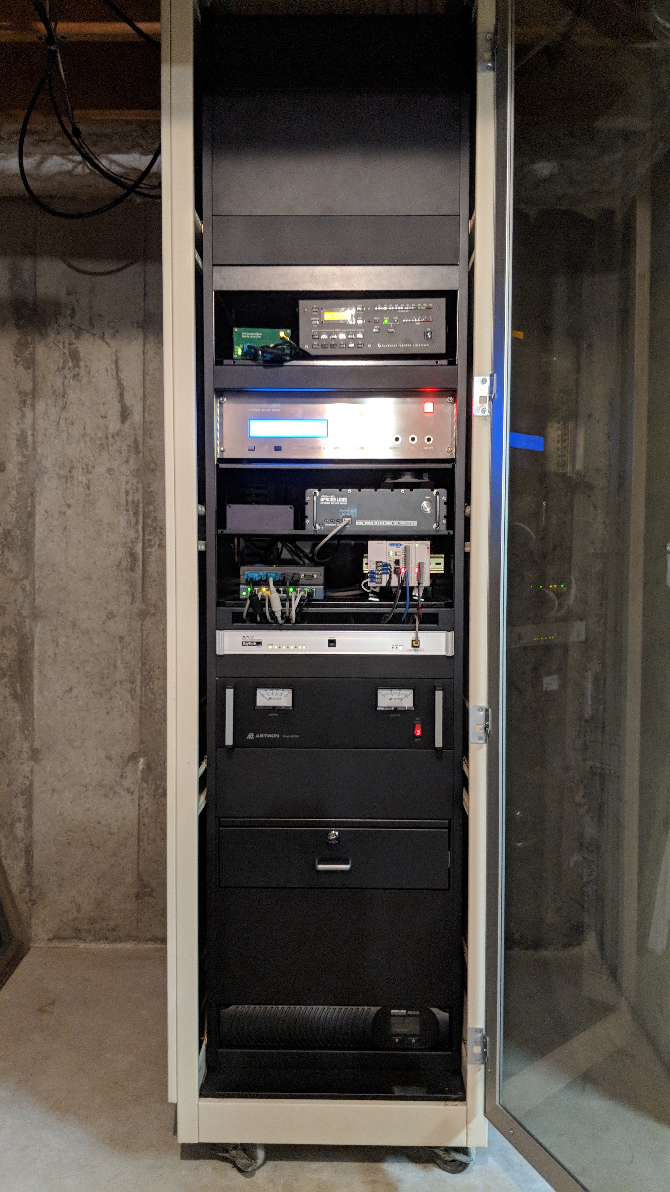
The WU2O station is physically contained within a 7 foot, fully enclosed, AMCO equipment rack located in the basement. It is operated from a separate, second floor studio via a single, hardwired Gigabit Ethernet LAN connection. This is possible because the most of the equipment can be remote controlled via Ethernet, either directly or via an RS-232 device server.The rack provides an excellent environment for superior grounding, bonding and EMI/RFI control. Its location in the basement, and its fully enclosed design including a full height plexiglass front door, keeps fan and relay noises well contained, and mitigates the accumulation of dust on the equipment. The basement location maintains a temperature right around 65 deg. F all year and, combined with the controlled ventilation inherent this type of rack, keeps all equipment within temperature limits even at high duty cycles.
Be sure to click on the photos above and below for a closer look.
Rack Organization & Construction
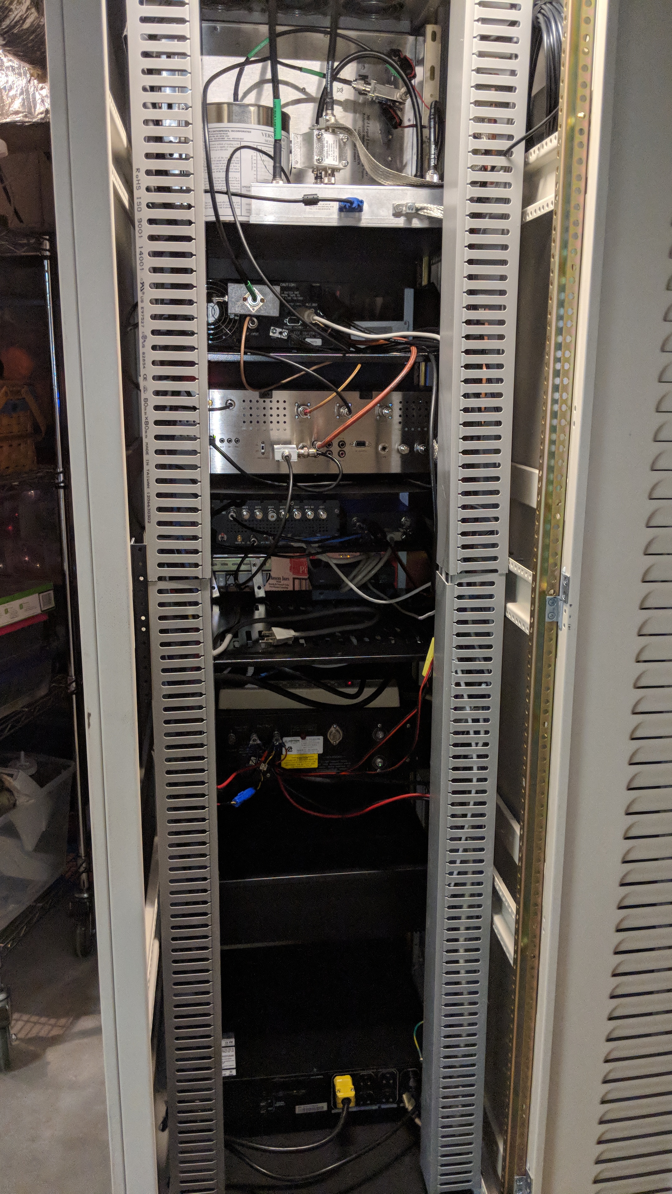
The rack is organized in a logical fashion so that signals largely flow from bottom to top. The bottom section contains power supplies and other supporting hardware. The middle section contains communications, command and control equipment, the radio hardware, and the amplifier. The top section houses RF routing and antenna interface equipment.Even racks can become a rat's nest of cabling that presents maintenance and configuration management nightmares. To prevent such an occurence not only is the equipment organized in a logical fashion, there are also wire management ducts provisioned on both sides in the rear of the rack, and a full height copper ground bar. This allows segregation of AC power in the left duct, 12VDC power, LAN and serial cables in the right duct, and RF connections in the middle of the rack. All cable lengths are managed so that there are no large rolls of excess wire. All external connections come into the rack through the top, with sufficient service loop such that the rack can be spun 360 degrees on its wheels for ease of maintenance. An LED lightstrip is mounted at the top of the rear area to provide sufficient light to work in the rack easily.
Top Section: RF Routing & Antenna Interface
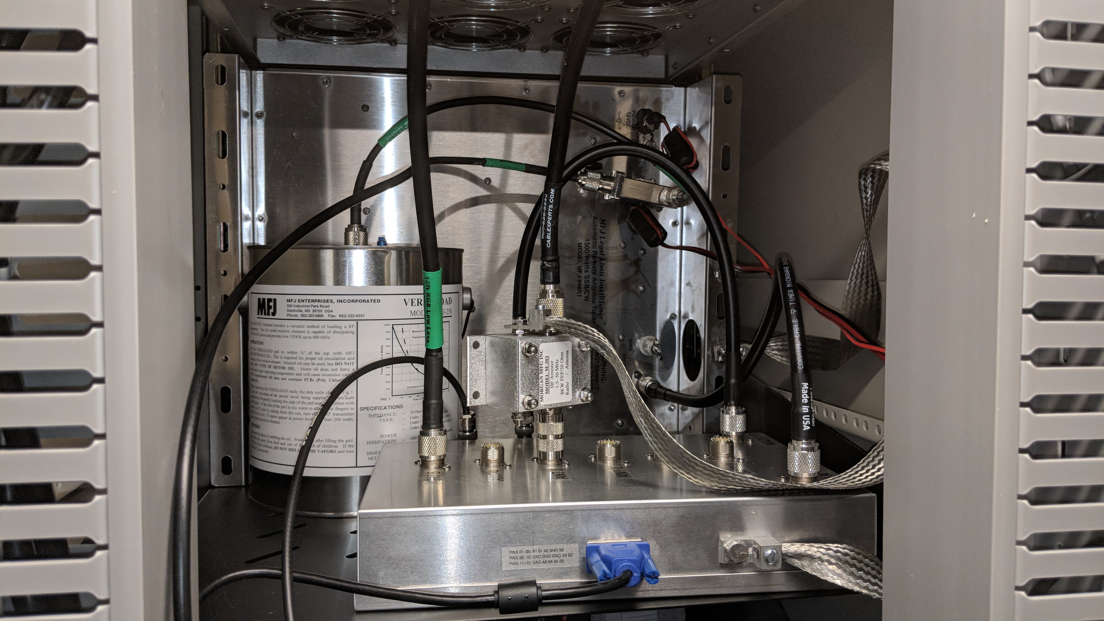
The equipment in this section, consisting of a wide variety of shapes and sizes, was not so easily organized. Hence it is simply mounted on a rack shelf behind a large blank panel near the top of the rack. Placement near the top of the rack minimizes the intrusion into the rack of cables and equipment carrying higher RF transmit power levels.Antenna routing to the radio hardware is provided by homebrew 2x6 antenna switch using a circuit board produced by KK1L. This is set up to route either the inverted L or the dipole array to the antenna tuner, and the remaining antenna to the ANT2 connection on the radio so that it may be used for receive. Normally the dipole array is used for transmit and receive on 40M and higher. On 60M and below it is used for receive while transmitting is done via the inverted L.
Antenna tuning is accomplished using an MFJ-998RT remote antenna tuner. While not truly a "remote", e.g. tower-mounted, situation, it nevertheless is a good choice given that the station is operated from a separate studio. The tuner can be remotely reset for "from scratch" tuning.
Rather than placing the dummy load on a spare antenna switch port on the antenna side of the tuner, a separate CX600M coaxial relay switch is mounted on the tuner radio-side input to route RF to either the tuner or the MFJ-250 can-type dummy load. This allows quickly switching between the dummy load and an already tuned up tuner without having to mess with re-tuning.
The full height ground bar is hidden behind the cable duct, but the heavy braid that bonds equipment to the ground bar and the 6AWG mechanical lugs used on the equipment ends are easily visible. The mechanical lugs are the best thing since sliced bread and easily work for the braid and the 6AWG high strand count, very flexible copper "welding cable" that I prefer to use for grounding and bonding.
For more information on how this is all controlled, see below.
Amplifier & Radio Hardware
Between the radio hardware and the RF routing and antenna interface is, quite naturally, an ampliifer, an Elecraft KPA-500. The KPA-500 is a good choice because it is well supported by an Elecraft remote control software application. There is a spacer above the KPA-500 that reserves ample room for potential future amplifier upgrades such as the B26 RF-2K+ or possibly the Elecraft KPA-1500.The output of the KPA-500 is provisioned with a very early model Xtronic high power coupler (mine pre-dates what is currently sold at HRO) to provide a feedback signal for linearization processing in the radios.
Next to the amplifier is an inexpensive, Chinese GPSDO built on the earlier BG7TBL design. No link is given because the cheap GPSDO market changes minute by minute, but you can find these and similar units on eBay for less than $150. This particular unit has a very nice, Russian-built, Morion ovenized crystal oscillator (OCXO) providing excellent long and short term stability. The 10MHz frequency reference output is distributed to both radio units using a Mini-Circuits ZFSC-2-4+ hybrid power divider.
The main radio hardware unit is an Apache Labs ANAN-8000DLE. I call it a "radio hardware unit" because most of the SDR functionality is in the thick-client SDR software residing on the PC. The hardware only contains the preselection and low pass filtering, ADC, DAC, power amplifier, and conversion to/from the first (and only) IF. It is the IF data that moves between the hardware unit and the software on the PC.
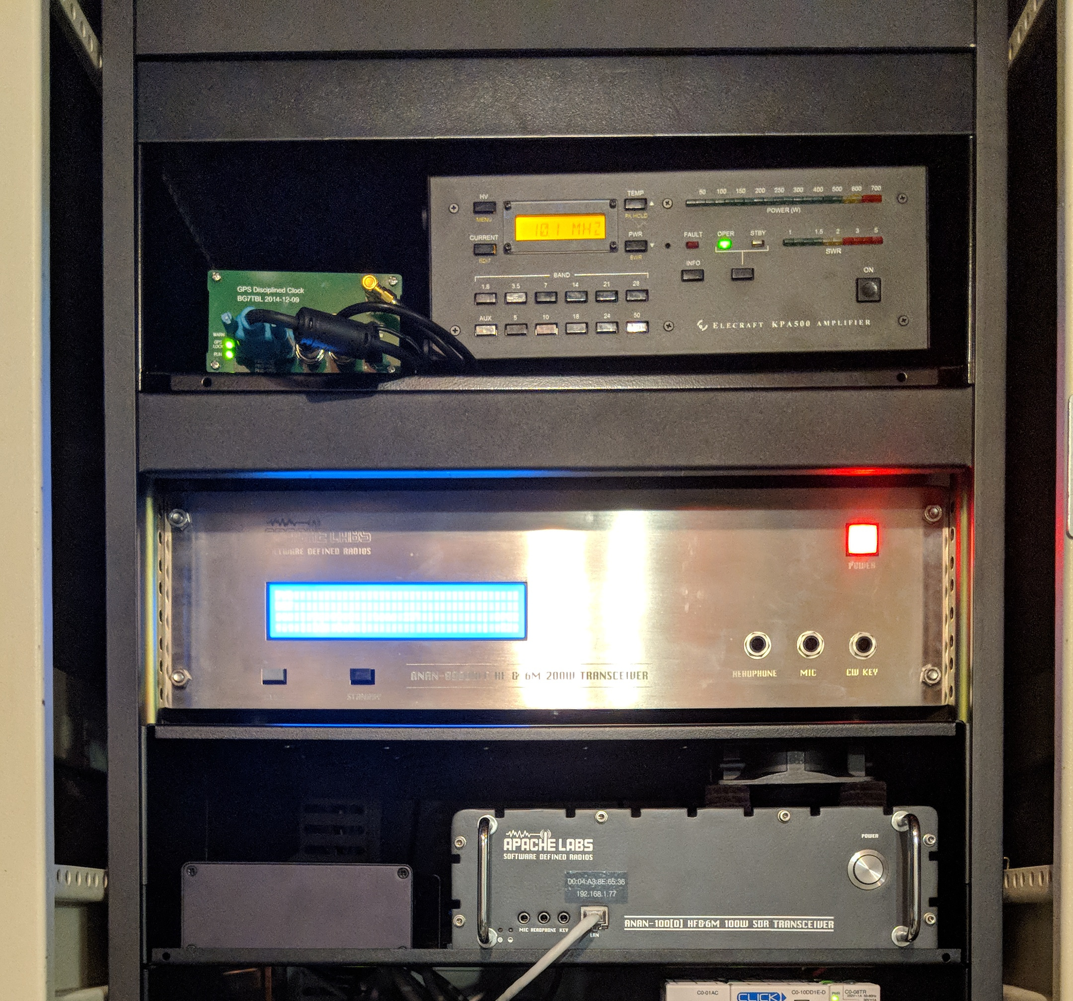
Below the primary radio unit is a modified Apache Labs ANAN-100D, which serves as backup. The modifications to this unit are described on the ANAN-100D projects page.
Remote Communications, Command & Control
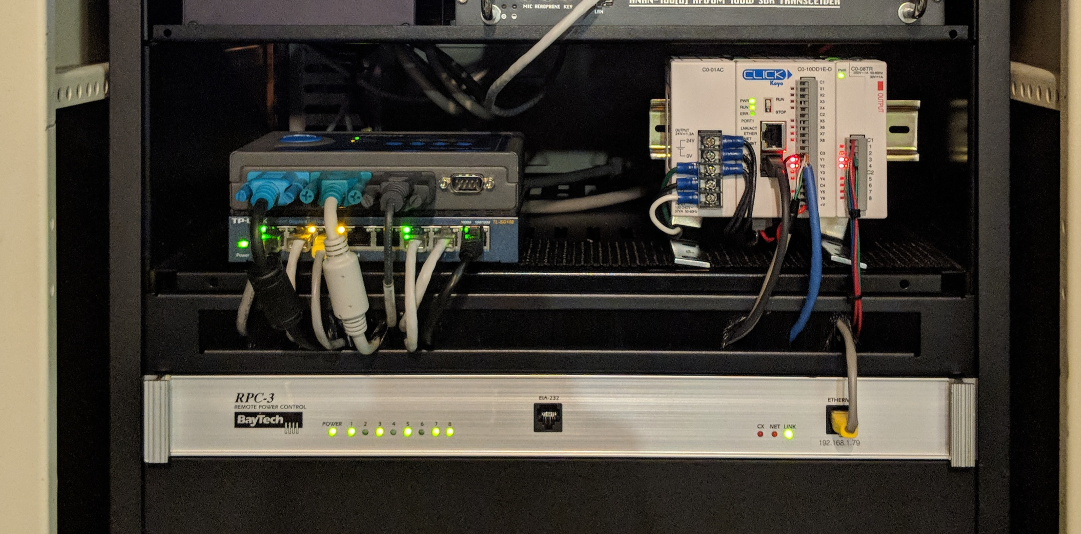
When your entire station is not directly at hand some thought must be given about communicating with and controlling everything. However, it is not as difficult as you might think.There is, of course, a Gigabit Ethernet switch to consolidate Ethernet connections for uplink to the main house switch. There is little that is noteworthy about this piece of equipment other than to say that a unit with a metal chassis was chosen so that it might be properly bonded to the main rack ground bar.
More importantly, placed on top of the GigE switch is a Moxa Nport 5450I serial device server. With most amateur radio equipment continuing to cling bitterly to the elderly RS-232 serial communications standard, a method of remotely connecting the PC in the studio to these devices is necessary. Moxa makes a vast line of these servers and the Moxa driver software makes the remote nature of each serial port completely transparent to the PC operating system. Invaluable and highly recommended.
The real star of the show where remote command and control is concerned is the programmable logic controller (PLC), which is the white unit on the right. This is an Automation Direct CLICK series PLC, model number C0-10DD1E-D. It is equipped with a CLICK series power supply and two relay units. In combination with the highly capable DDUtil middleware software, the relays of this PLC control nearly all switching functions of the station, including the 2x6 antenna swtich, dummy load coaxial relay switch, tuner power (used for reseting the tuner), radio hardware programming switches, etc. Some of these functions are automated by DDUtil, for instance the antenna switching. Other functions are manually controlled via macro buttons in DDUtil, for example the dummy load coaxial relay. This capability is so much easier and less complex to implement than a random collection of "internet controlled switches", Arduinos and other nonsense, much more highly integrated with the SDR, and far less expensive as well!
Lastly, there is a Baytech RPC3 network controlled power strip to provide remote switching of all AC powered items in the rack. This is controlled by a cool little software application available here. These units are no longer in production, but they are available inexpensively on eBay.
Bottom Section & Power Supplies
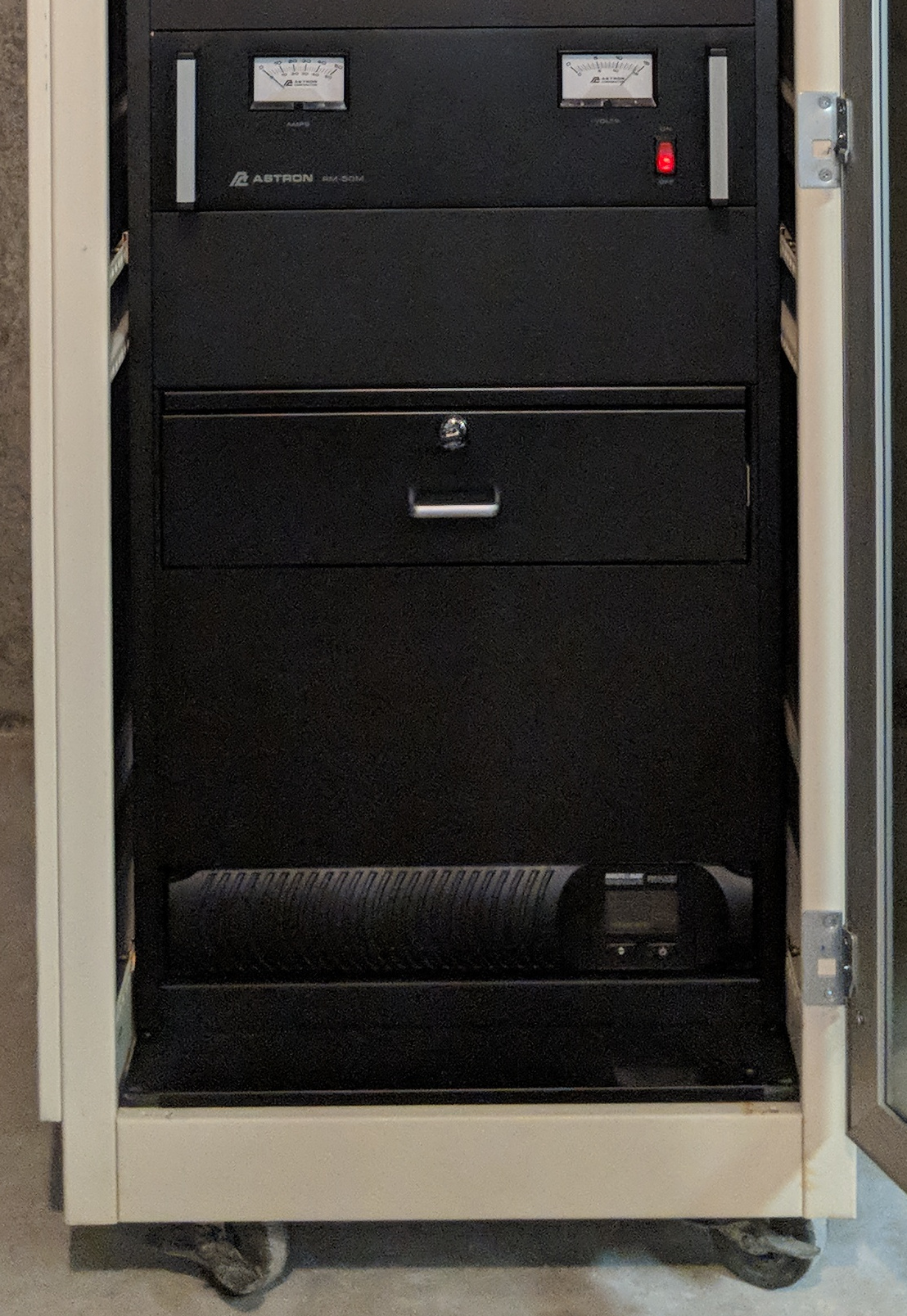
At the very bottom of the rack, because it is so heavy, is a large, Minuteman PRO1500RT 1500VA UPS. This UPS is large enought to easily run everything in the rack until the whole-house generator can take over the load in the event of a power failure. I also find them to be a key part of my lightning protection strategy. Indeed, nearly every large electronic device in the house (television, etc.) is protected by a UPS. Plus the house uses a Leviton whole-house surge protector.The main station power supply is the ubiquitous Astron RM-50M.
The remainder of the bottom section of the rack remains as growth space. Blank panels are provided not just for appearance purposes, but also to promote proper airflow through the rack. There is also a storage drawer to hold such things as tools, test cables, adapters, fuses and other spare hardware close at hand.
# # #