The station sports two, relatively simple, wire antennas, a modified dipole array, and an almost inverted L.
Antenna 1: 10M-40M wire dipole array (sort of...)
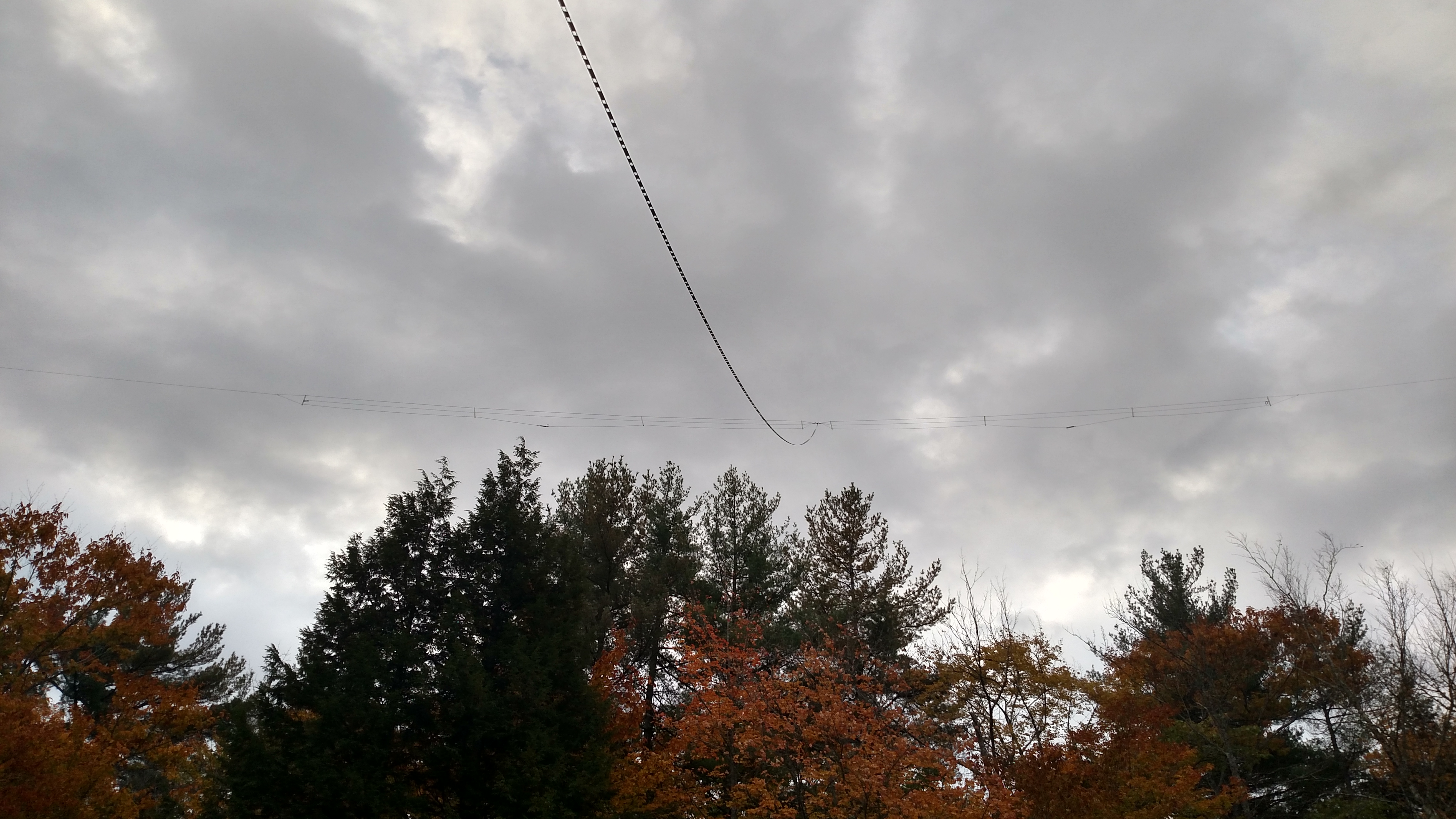
Antenna 1, pictured above, is a three element array suspended at an average height of about 65 feet, between two tall trees. It started life as a simple 20/40/80M multi-band dipole. It is fed with 115 feet of 450 Ohm window line in order to support non-resonant use on all amateur HF bands. The window line terminates into a DX Engineering DXE-BAL200H10AT 4:1 current "tuner" balun, mounted on the eave of the house. The DX Engineering baluns are pretty much bulletproof. The 5KW rating of this balun happily deals with some of the sportier voltages that can happen on some of the less resonant frequencies. 25 feet of LMR400 coaxial cable bridges the gap from the eave-mounted balun to the Morgan M-303 lighting arrestor mounted on a ground rod, then another 25 feet of LMR400 leads to the station in the basement. A few snap-on ferrites on the coaxial cable where it exits the balun form a choke to deal with any potential shield currents caused by non-resonant operations.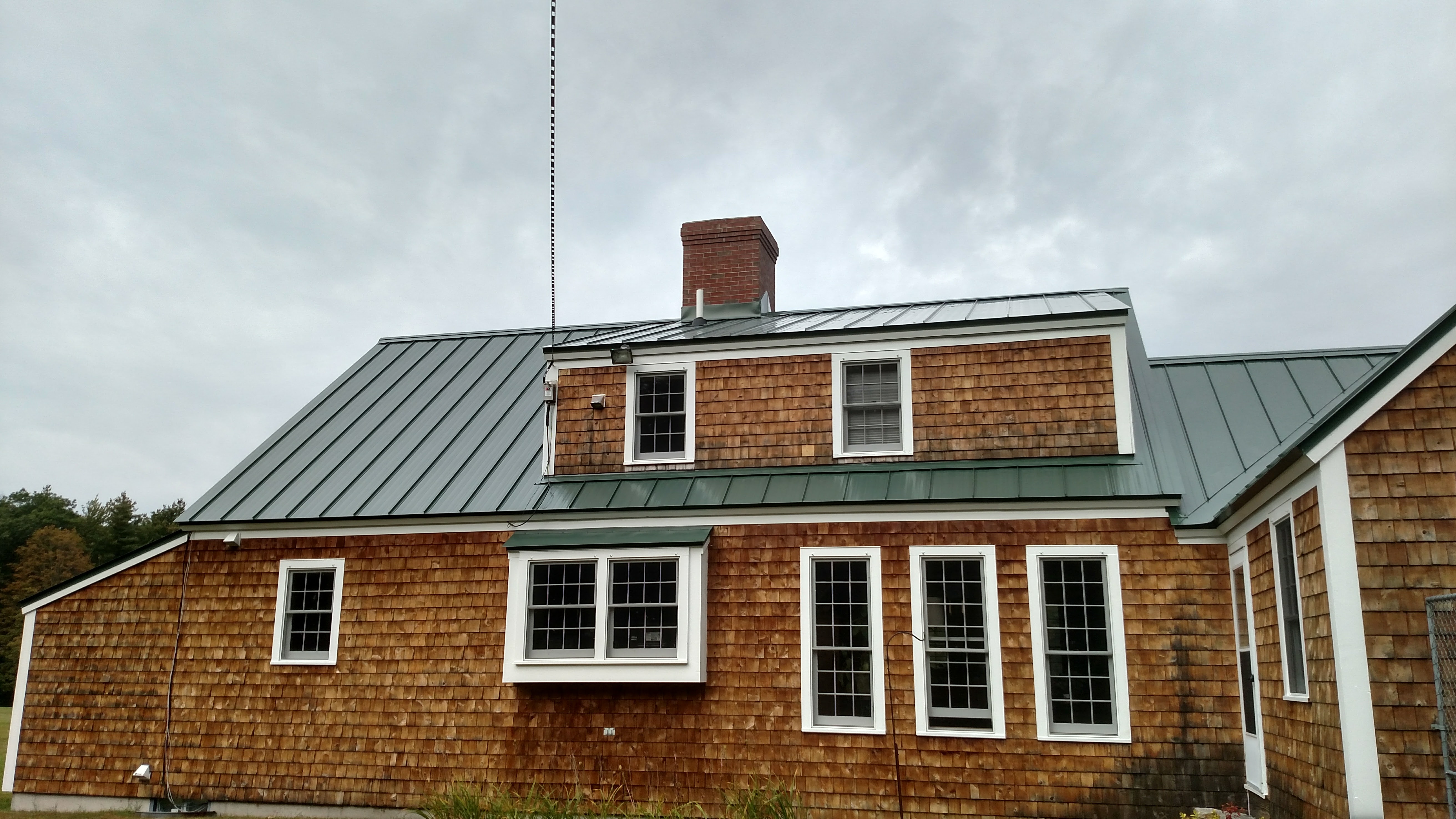
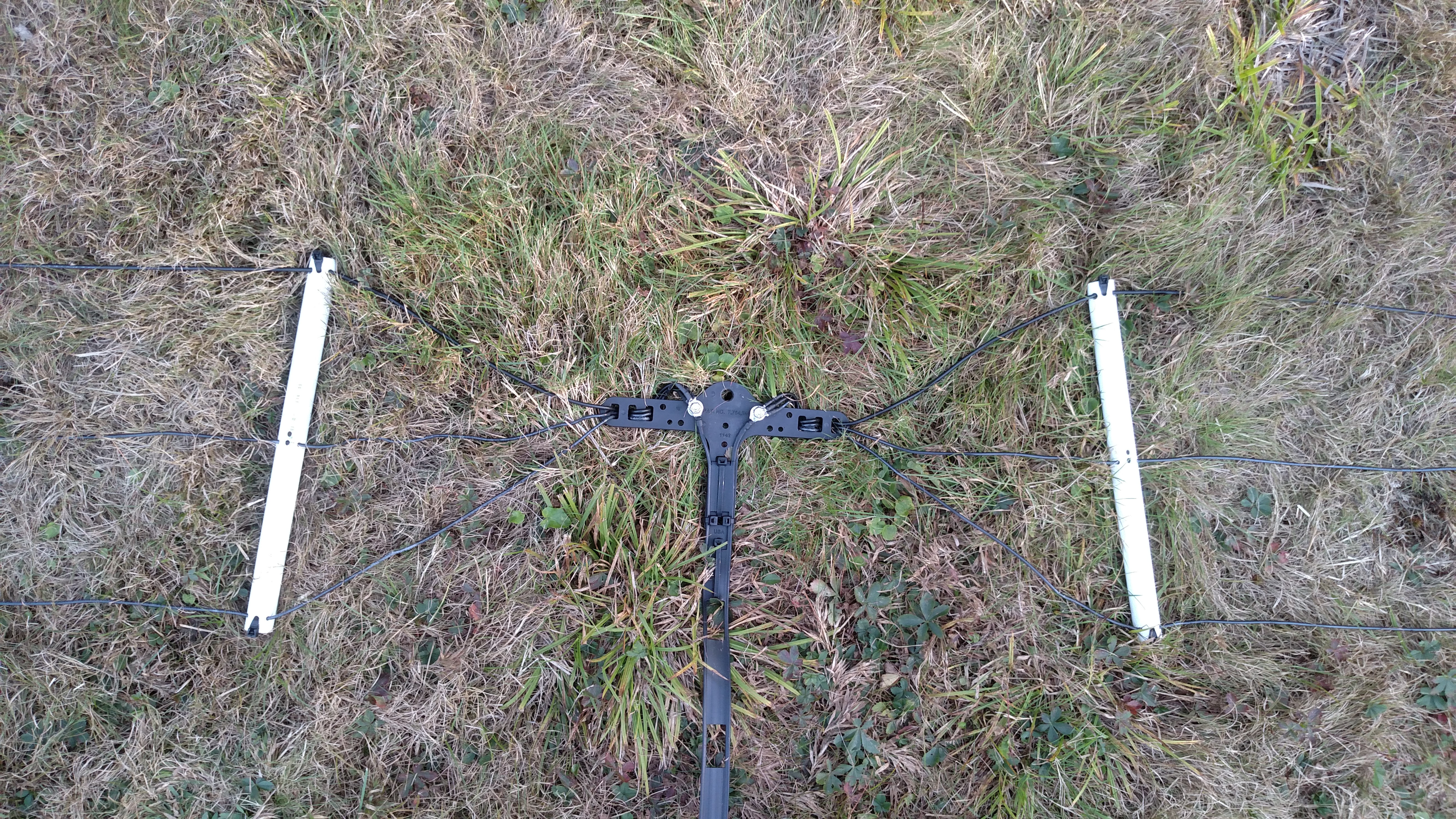
The antenna is physically constructed using 13AWG copper-clad steel wire ("copperweld") on the main (top) element for strength. The other elements are built from 14AWG THHN (insulated, stranded, copper). Spacers are constructed from 1/2" PVC tubing. The center and end insulators and ring terminal hardware came from a DX Engineering kit. The vertical elements use a couple of hardware store plumb bob weights on the ends to keep them nice and straight.
There are no pulleys used. 7/16" Dacron line is lead directly over tree branches for the halyards at each end. Combined with the 13AWG copperweld this has held up very well in some very serious ice storms. The halyards are replaced every three years or so to avoid breakage due to wear. There are 550 cord tag lines on the vertical elements to assist in keeping them under control in the wind. Extra 550 cord pull lines are already in the trees in case disaster should strike.
The arrangement of the available trees caused the dipoles to have lobes that were primarily north and south, and the antenna was fairly directional on 40M. I wanted the ability to work into Europe on 40M. I ran a few ideas through EZNEC. EZNEC is some absolutely invaluable antenna modeling software and everyone should have a copy and know how to use it. As a result, I ultimately modified the 80M element to include a vertically suspended element at each end that is a quarter wavelength on 40M. This turned the antenna into an almost omni-directional radiator on 40M, sort of a modified half-square antenna. It has proven to be a very good performer with relatively low elevation angle radiation. As you might expect, the modification of the 80M element made it difficult to use the antenna on 80M, and the tuner basically had to beat it into submission. That problem, and the additional desire to be able to operate on 160M as the solar cycle continued to decline in the late twenty-teens, caused the second station antenna to come about.
Antenna 2: 160M almost inverted (lazy) L
There is nothing too scientific about this antenna design. No EZNEC analysis was done or anything like that. A 7/16" Dacron halyard was thrown over a tree limb about 90 feet up and used to haul up a large, 7" diameter pulley. The large diameter is to keep the stress low on the wire as it turns the corner. There is also a tag line so the pulley can be brought down for maintenance. 155 feet of 12AWG THHN is led from a 15 foot high elevated feed point on the opposite eave of the house from the other antenna to the pulley, which sits at about 75 feet up. After going through the pulley the intent was to arrange something similar in another tree for the horizontal part of the L. Right now it is "lazily" brought away from the pulley at about a 45 degree angle with a long length of 550 cord to a short tree. There are two elevated radials, again not analyzed, just convenient lengths to nearby trees. 100 feet of LMR reaches back to the station. No balun is used, the feedpoint is just a box with an SO-239 mounted in it. The antenna tunes up well on 60, 80 and 160M. Signal reports are good. It is, however, horribly noisy on receive. Therefore it is only used for transmitting. Reception on those bands is performed using Antenna 1, which is very quiet and performs quite well for that. Switching between transmit and receive antennas is a built-in function of the radio, so using the antennas this way is easy.Future plans
There is much room for improvement here, antenna-wise. The to-do list includes:- Making the top part of the L horizontal.
- Getting another tuner and moving the remote tuner to the feedpoint of the L.
- Revisiting the elevated radial design (using EZNEC).
- Putting up some beverage antennas (I have plenty of room for this).
- Fabricating a better house entry point.
# # #