How to Use Virtual Audio
with PowerSDR mRX PS
WU2O January 2017
1.0 Introduction.
"Virtual audio" is a catch-all term that has primarily come to mean sourcing and playing back audio via the PC that is running PowerSDR rather than from a microphone or speaker that is attached directly to the radio. Audio is sourced or played back at the PC either from a hardware sound interface attached to the PC or from other sound-related software running on the computer, such as a digital mode program like Fldigi, or digital audio workstation (DAW) software like Ardour, Audiomulch or Pro Tools.
Virtualization may also be accomplished for PTT and CW keying, i.e. it is not necessary to have a PTT switch or a key directly attached to the radio. Indeed, the PC and operating location can be quite far away from the radio room or shack, and need only be connected to it by Ethernet.
This tutorial covers virtualization with PowerSDR mRX PS, i.e. the openHPSDR version of PowerSDR, not to be confused with the old, legacy version of PowerSDR that was used with the 5000 and older series of Flex radios, nor SmartSDR, used with the current version of Flex radios. Nevertheless, much of this material is also applicable to the legacy version of PowerSDR used with the legacy Flex radios.
2.0 This document is divided into the following parts.
- A review of the functional basics, rules and software limitations associated with the PowerSDR virtual audio interface.
- Suggestions for testing and tuning system performance for real-time audio.
- How to quickly setup a USB headset for use with PowerSDR.
- Virtual PTT switching for virtual audio.
- Latency: what it is and how to minimize it.
- How to setup up Voicemeeter Banana and interface digital mode software audio streams.
- Virtualizing CW operations.
- Integrating Digital Audio Workstation (DAW) software.
3.0 A review of some of the functional basics, rules and
software limitations of the PowerSDR virtual audio interface.
Historical note: originally, in the legacy Flex radio days, the VAC interface was seen only as a mechanism to allow access for digital mode programs, voice keyers and the like. As such, it was optimized for those uses. Unfortunately, little has changed in this area even though a much larger number of PowerSDR users now seek to virtualize their operations.
Understand that "VAC" within the context of PowerSDR, no longer needs to mean "virtual audio cable".
The term “VAC” came from the original software application that allowed different sound enabled applications to talk to each other without having to physically wire two separate hardware audio interfaces to each other. This software was written by Eugene Muzychenko and was, and still is, called “Virtual Audio Cable”. There are now at least two other choices besides Eugene Muzychenko's Virtual Audio Cable software. Someday, perhaps, the user interface on PowerSDR should be changed to denote "DA1" and "DA2", for "digital audio". And, not only can this interface carry normal audio information, it can also be used to exchange raw I/Q digital IF data.
RX1 audio will ONLY appear on the VAC1 interface. RX2 audio will ONLY appear on the VAC2 interface.
While handy for those who want to run multiple instances of something like WSJT-X JT65 software, for example, this creates problems for those who simply want the VAC interface to act like the speaker output on the radio.
If you want to use ASIO sound drivers then you can ONLY have one instance of it, either on VAC1 or VAC2.
Another limitation of today's PowerSDR that someday might be improved upon, which is unfortunate because the ASIO sound driver is a very low latency sound driver that is supported by most professional audio interfaces and nearly all digital audio workstation (DAW) software. ASIO allows real-time audio in a PC environment.
The MUT button has no effect on VAC audio.
The intent here was for digital mode operators to be able to mute the radio speaker output without affecting the audio stream to the digital mode software. Again, handy for that use, but this feature is sorely missed for those who simply want the VAC interface to act like the speaker output on the radio.
The Master AF slider has no effect on VAC audio.
The intent here was for digital mode operators to be able to adjust the radio speaker output without affecting the audio stream to the digital mode software. Again, handy for that use, but this feature is sorely missed for those who simply want the VAC interface to act like the speaker output on the radio.
MIC (gain) settings have no effect on VAC inputs.
You have to use the TX Gain setting in the VAC setup, or, if you have DIGU selected, the VAC TX Gain setting in the main user interface. The original design intent here was primarily associated with contest voice keyers. This way the gain for a radio attached microphone could be maintained separately from the voice keyer gain. Once again, handy for that use, but this feature is sorely missed for those who simply want the VAC interface to act like the microphone input on the radio.
ALL other audio processing (COMP, EQ, DEXP, Leveler, CFC, CESSB, ALC, etc.) works on VAC audio in LSB, USB, AM and SAM.
ALL audio processing (except VAC RX Gain, VAC TX Gain and ALC) is disabled on VAC audio when in DIGU or DIGL.
There is NO CW sidetone available on the VAC interface.
This is an unfortunate side effect of the high latency that used to be present on this interface but is not anymore. It's another area ripe for improvement in future versions of PowerSDR. A work-around for this is suggested in the section on virtual CW operations below.
4.0 Suggestions for testing and tuning system performance
for real-time audio.
It is very strongly suggested to install and run two
tools to check your system for audio performance factor before proceeding further:
5.0 How to quickly setup a USB headset for use with PowerSDR.
This is perhaps the most basic exercise one can perform, and it is a good introduction to virtualizing your audio. It may be all you need or want. There are many advantages of this method over a radio attached microphone. It allows you to avoid having to figure out:
- What speaker and microphone to use
- How to make the cables to attach them
- How to
take the radio apart to set the jumpers (no need for this on the 200D, 7000 or 8000)
- How to set the mic settings/jumpers properly.
Instead you can plug in a simple USB headset and be up and running in just a few minutes. The following instructions should work for most headsets or any pair of Windows audio devices. Even if your chosen device uses a slightly different set of options in the Windows Sound Control Panel than those shown below, this should still be enough of a guide to get things working quickly and well.
Before starting ensure that all software that will use
the headset is not running, e.g. PowerSDR.
Step 1: plug in a USB headset to your computer. Make certain it installs correctly of course, i.e. that you don't get any driver error messages, etc.
Note: once you choose a USB port to plug the headset into
always be sure to plug it into the same port. The funny thing about USB devices
is that they will install themselves as a different physical device if you move
them to another port. This will tend to screw things up and require you to go
through some or all of this setup guide again.
Step 2: open the Windows Sound Control Panel, go to the Playback Tab, and find your Headset Earphone. In the Figure 1 you can see my Microsoft Lifechat LX-3000 headset as an example.
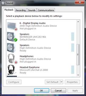
Figure 1—Example of Windows Sound
Control Panel Playback Tab.
Step 3: double click the Headset Earphone device in the Playback Tab to open Headset Earphone Properties, select the Advanced Tab as shown in Figure 2, and adjust the Default Format to 2-channel, 16-bit, 48000 Hz (DVD Quality). The reason that 48KHz is preferred is because that is the native, internal sample rate used for audio in PowerSDR. Choosing this sample rate avoids the necessity for PowerSDR to do sample rate conversions. 2-channel (stereo) is also preferred so that the mono output from PowerSDR will be heard in both ears or sent to both speakers, and to allow the use of the stereo pan features in PowerSDR.
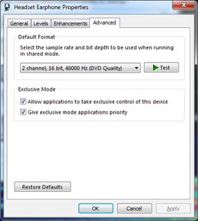
Figure 2—Headset Earphone Advanced
Properties Settings.
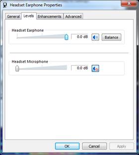
Figure 3—Headset Earphone Level Settings.
Step 5: select the Enhancements tab and turn off all enhancements as shown in Figure 4. You may ultimately want to experiment with these, but initially it is recommended to leave them off.
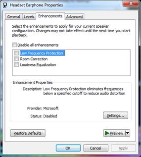
Figure 4—Headset Earphone
Enhancement Settings.
Step 6: click OK to close the Headset Earphone Properties window but don't click OK again, leave the Windows Sound Control Panel open because now similar settings need to be done on the recording side and for the same reasons.
Step 7: select the Recording Tab in the Windows Sound Control Panel and find your Headset Microphone. In the Figure 5 you can see my Microsoft Lifechat LX-3000 headset as an example.
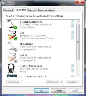
Figure 5—Example of Windows Sound
Control Panel Recording Tab.
Step 8: double click the Headset Microphone device in the Playback Tab to open
Headset Microphone Properties, select the Advanced Tab as shown in Figure 6,
and adjust the Default Format to 1-channel, 16-bit, 48000 Hz (DVD Quality).
Also check both boxes under "Exclusive Mode".
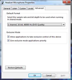
Figure 6—Headset Microphone Advanced
Properties Settings.
Step 9: select the Levels tab and adjust the Headset Microphone level to maximum as shown in Figure 7. Note: you can change from percent to dB by right clicking in the numerical display box.
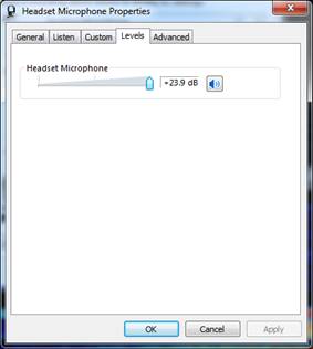
Figure 7—Headset Microphone Level Settings.
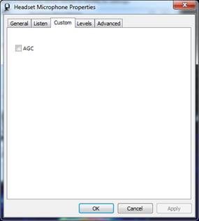
Figure 8—Headset Microphone Custom Settings.
Step 11: click OK to close the properties window and then click OK again to close the Windows Sound Control Panel.
Step 12: start PowerSDR but do not click the "POWER" button to start the software. Note: it's best to have PowerSDR software in the "POWER" off state when changing VAC settings. By this I mean that the "POWER" button in the main PowerSDR user interface is not illuminated, not that you have to physically turn off the radio. The software is sometimes intolerant of changing VAC settings during operation and can crash.
Step 13: open the Setup window and select the Audio > Primary tab. Make the primary buffer setting 2048, which is a very conservative setting to start with.
Step 14: open the Setup window and select the Audio > VAC1 tab. Make all settings as shown in Figure 9, which uses my Microsoft headset as an example device:
Enable VAC 1 box: checked
Driver: MME (it's the most reliable and easiest driver to start with)
Input: Your microphone device
Output: Your earphone device
Buffer Size: 2048 (a very conservative setting to start with)
Sample Rate: 48000
Gain (dB) RX: 0
Gain (dB) TX: 0
Stereo checked
All other checkboxes: unchecked
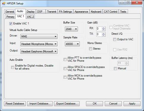
Figure 9—openHPSDR VAC1 Settings.
Step 15: click OK. Then click "Power" on the main GUI. Now you should be in business! It should not have taken more than 5 minutes to get to this point.
Step 16: check your received audio quality. Adjust your volume using some combination of Windows headset volume controls and the RX1 AF control. At this point you should be able to hear your receiver audio quite clearly with no drop-outs or other artifacts.
Step 17: understand your receiver audio adjustments. As discussed in Section 3 above, receive audio processing has a few noteable differences when using VAC1 instead of the speaker jack as a receive audio interface.
- Controls that work the same as when using a speaker: RX1 AF, RX EQ, and MultiRX for VFO A & B
- Things that don't work: RX2 audio will not appear on VAC1. The Master AF control will not affect audio. MUT does not work either.
RX2 audio appears on VAC2. If you want to hear both RX1 and
RX2 then you will need to use an audio mixing application like Voicemeeter
Banana.
Step 18: decide how you are going to implement push-to-talk (PTT). For now, just use either the MOX button on the main GUI or the spacebar on the keyboard (make sure the spacebar is selected for PTT in Setup > Keyboard). You can also use VOX, of course. See also Section 6 below to virtualize a physical PTT switch.
Step 19: adjust your transmit audio settings. This is no different than it would be with a microphone plugged into the front panel with one exception: the MIC gain setting on the main GUI does not work with VAC audio—you must go into the VAC setup window and adjust TX Gain instead.
Rob, W1AEX, has written the most comprehensive guide on how to properly set up your audio in PowerSDR. Proper distribution of gain is easy to achieve, but nevertheless critical throughout all of the various stages of audio processing in PowerSDR. This is true whether you are using a regular microphone attached to the radio, or virtualizing your audio through VAC. Rob's outstanding guide can be found at this link:
You must also remember that in order for PureSignal to work the ALC must hit 0dB with some regularity. Seeing it go to +1 or +2dB on the ALC Comp meter is just fine. Also bear in mind that the ALC meter only reads to 0dB maximum, while the ALC Comp meter only reads to 0dB minimum. You must look at both meters to know exactly how much ALC is being invoked. Why the developers did not combine these two meters as in a regular radio I could not possibly say.
Transmit audio adjustments: as long as LSB, USB, DSB, AM or SAM are selected, COMP, VOX, DEXP, TX EQ, the leveler, CFC and CESSB will all operate on the audio from your headset coming through the VAC1 interface, as described in Section 3 above. Again, the only difference is that MIC gain settings do not work, you must adjust TX Gain in the VAC1 setup window instead.
You may find that the typical USB headset requires some enhancement in the upper frequency ranges. The built-in TX EQ capability in openHPSDR can accomplish this handily as shown in Figure 10.
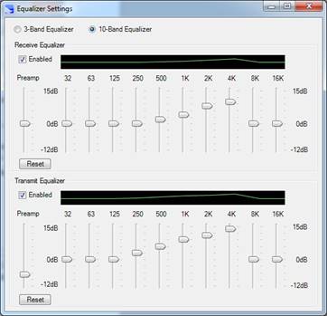
Figure 10—Example TX EQ Settings.
Step 20: check your transmitted voice quality. This is a very important and often overlooked step. Obviously if something is wrong with the receive audio you will clearly know right away. But you might not know if something is wrong with the transmit audio going out. To check your transmitted voice quality turn on the MON button in the PowerSDR main user interface and listen to your own voice going out. When you make a transmission you will hear your own voice with quite a bit of delay on it. If something has gone wrong with the VAC interface it will sound pretty horrible. If PureSignal is turned on it may sound "funny" because it has already been pre-distorted by PureSignal, but it won't sound like "Mr. Roboto". You can temporarily turn off PureSignal to get a true representation. If transmit audio does sound terrible this is because the VAC buffering in PowerSDR did not initialize properly (a known bug). The solution is to cycle the "POWER" button in PowerSDR to OFF and then back ON again. Sometimes it may also be necessary to restart PowerSDR.
Most people find it impossible to operate with MON turned on all the time. But do use it occasionally just to keep an ear on things.
Step 21 (optional): adjust your buffer settings for lowest latency. In the steps above the buffer sizes were set to 2048. This is the safest, most conservative setting. The intent in setting it to 2048 initially was to facilitate getting things running smoothly on the first try. However once things are running smoothly, there is some benefit in making adjustments to achieve low latency in the audio processing chain. If you are using an audio interface that supports ASIO drivers, it is possible to obtain better latency performance than with a microphone and speaker attached to the radio! See Section 7 below for more information.
6.0 Virtual PTT switching for virtual audio.
While the MOX button, spacebar and VOX are all nice options for PTT control, sometimes there is no substitute for the ergonomics of a nice desk or foot switch. PowerSDR provides a facility for virtualizing a physical PTT switch. What is required is a serial port on the PC. This can be a USB-to-serial adapter, or a physical card, or a motherboard connector. As long as the serial port properly supports the flow control pins on the interface it will work fine.
Step 1: open the Setup window and select the CAT Control > CAT tab. Choose the correct port number for PTT control, RTS as the PTT signal, and check the Enable PTT checkbox.
Step 2: assuming the PC uses a standard 9 pin, D-subminiature serial port connector, build a switch-cable-connector assembly such that the PTT switch will connect pins 7 and 8 together when pressed.
It is worth noting that if you are educated in the ancient and archane ways of RS-232 signalling, you will no doubt find that the "RTS" option in the PowerSDR setup tab can be quite confusing. On the PC, Request To Send (RTS) on pin 7 is actually an output, of course. When RTS is selected as the PTT signal the PowerSDR software actually uses the assertion of Clear To Send (CTS) on pin 8, which is an input on a PC, to sense whether the PTT switch has been closed. Since on a PC the RTS signal is normally asserted, it can be used as a convenient source of RS-232 signal level to input to the CTS pin. Why the developers chose to call this method "RTS" is not clear. Similarly, if you for some reason chose the Data Terminal Ready (DTR) method, this actually requires that a signal be asserted on the Data Set Ready (DSR) input on pin 6.
7.0 Latency: what it is and how to minimize it.
Transmit latency is the time that elapses between when your voice hits the microphone element and the corresponding modulated RF comes out of the antenna port. Similarly, receive latency is the time between when the modulated RF enters the antenna port and the corresponding audio comes out of the speaker. Latency is a negative attribute and a fact of life with software defined radios (SDRs). Latency can reach large enough values to make things like breaking a pile-up very difficult, or preventing ARQ type digital modes from working. It can also severely impact CW break-in operation.
Compared to an analog radio, a software defined radio (SDR) will always have greater latency. The main reason for this is two-fold. First is that audio information tends to be processed in chunks. These chunks are often user-definable, i.e the buffer sizes that are set define the size of the chunks. For example, at a 48KHz sample rate, a buffer of 2048 samples will take 42mS to fill. Analog radios don't process information that way, their delays are measured in the sub-millisecond range. Second is that digital filtering can take many sample clock cycles to process. For example, the delay of a linear phase finite impulse response (FIR) filter, a very common filter type used in SDRs, is (N-1)/(2*Fs) where Fs is the sampling frequency and N is the number of taps. So for a 2048 tap filter of this type at 48KHz sampling rate, the delay is 21mS. While there may be group delay in an analog filter, again it is typically just a few milliseconds or much less.
Thus, as you can see, the number, size and type of buffers, filters and sample rates is critical in controlling latency in an SDR. Use a lot of them, and/or make them too big, and pretty soon the SDR will exhibit some very large latencies. In PowerSDR specifically, using very conservative settings (large buffer sizes) it is not unusual to obtain 100mS or more of latency in each direction, both transmit and receive. If you consider two way latency, i.e the time that elapsed from the moment another station stops transmitting and you transmit in response, that can reach as much as a whole quarter of a second. On paper that might not sound like a lot, but of course that amount of latency will make it hard to break into a multi-way rag chew, break a pile-up, operate ARQ modes, or operate break-in CW. Such large latencies also make the MON facility impossible to use as sidetone.
The good news is that the developers of the PowerSDR software that runs on your PC, and the openHPSDR firmware that goes into the radios that we use, have spent a tremendous amount of effort to create ways that minimize latency. Unfortunately, minimizing latency requires some effort on the part of the operator to make the necessary adjustments. If PCs were all identical, the developers could preset all of the necessary parameters. But since there can be vast differences between operating system configurations, CPUs, memory and everything else that defines the ability of a PC to process real-time audio, such adjustments must be left up to the individual operator.
The other good news is that given a fast PC that is well tuned, and for virtualized audio an audio interface that supports ASIO drivers, it is possible to get both transmit and receive latency below 30mS, which is quite fast. It is adequate for real-time MON use, ARQ modes, and semi-break-in CW.
Below is the general process that I use to minimize latency in PowerSDR. There can be a lot of iteration. Honestly, in the end you may need to play some games and possibly go at it randomly. The ultimate goal is to use the smallest buffer sizes possible.
Step 1: VAC driver selection. ASIO is fastest but requires the use of an ASIO compatible sound interface with ASIO drivers properly installed. An excellent example is the Behringer UMC202HD. After ASIO comes WDM-KS. This is faster than MME, but much more sensitive in terms of its settings. MME is the slowest but the easiest to adjust.
Step 2: in Setup > DSP set all buffers to minimum (64) and select the low latency filter type. The linear phase filters are just that, filters with linear phase. The low latency filters are "minimum phase" FIR filters. Their phase response is not linear, but the delay through them is much faster. Given that the ionosphere makes dramatic differences in passband phase response by itself, there does not seem to be much benefit in selecting the linear phase filters anyway.
Step 3: in Setup > Audio > Primary set primary buffer to 64.
Step 4: set VAC buffer latency to ZERO and MANUAL. If you wind up in a place where you absolutely can't get anything to work, you can set this back to automatic, or set an arbitrary number in here. However any number above zero creates dramatic increases in latency.
Step 5: in Setup > Audio > VAC1 try to find a VAC buffer size that gives you receive audio that sounds good. If you can't achieve success at this step, jump to Step 7.
Step 6: given success in Step 5, listen to how you sound using MON and see if transmit audio sounds good, too. If you can't achieve success at this step, jump to Step 7.
Step 7: If you can't find a VAC buffer setting that works, increase primary buffer size one increment and try the process over again at Step 4. If you get to 2048 on primary buffer size and still haven't found a setting that works, increase DSP buffer size one increment and start over again at Step 3.
If you get that all working at 48KHz, consider moving to a higher audio sample rate if your audio hardware will support it. For, after all, a 2048 sample long buffer is half as much delay at 96KHz than it is at 48KHz. If you do try a higher sample rate expect to have to work the process over again.
Finally, in general you need to stay at 48KHz for digital mode software, as most digital mode software expects a 48KHz sample rate.
8.0 How to setup up Voicemeeter Banana and interface
digital mode software audio streams.
To interface to digital mode software without taking the brute force approach of installing two separate audio interfaces on the PC, one for PowerSDR and one for the digital mode software, and literally wiring them together, the idea of creating a set of virtual audio devices that could be connected in software was conceived. Eugene Muzychenko's Virtual Audio Cable software may have been the first to do this, I'm not sure, but it certainly has been the most popular method for a long time. Nevertheless I strongly recommend using VB Audio's outstanding Voicemeeter Banana (VMB) software in lieu of Eugene Muzychenko's Virtual Audio Cable software or VB Audio's own VB Cable. VMB has proven to be the most reliable and tolerant of mixing and matching drivers, buffer sizes and sample rates. It has a number of very useful features for monitoring audio and adjusting levels. It can even record and playback audio for you.
You can obtain VMB here: https://www.vb-audio.com/Voicemeeter/banana.htm. Be certain to obtain the "Banana" version and not the regular Voicemeeter version.
Please note that the following discussion addresses only the setup of the audio interfaces between PowerSDR and the digital mode software. CAT control of PowerSDR by the digital mode program is not discussed.
To setup VMB for digital mode operation, the steps are as follows:
Step 1: with all audio related programs including VMB closed, using Windows Sound Control Panel, open each VMB related audio device you see (e.g. "Voicemeeter Aux Input"), go to the Advanced Setting tab and set them to 16 or 24 bit, 2 channel, 48KHz. Be sure to do this for both Playback and Recording devices.
Step 2: open Virtual IO Control Panel and, using the Options menu, set the Internal Sampling Rate to 48KHz. Do the same for the Virtual Aux IO Control Panel. Reboot the PC.
Step 3: Start VMB. There is an optional setting in
VMB that has it run automatically when the PC boots. You may want to
turn that on for future convenience.
Step 4: Start PowerSDR and assign PowerSDR VAC1 to "Voicemeeter Input" and "Voicemeeter Output", 48KHz sample rate, MME driver, buffer size 2048, stereo, buffer latency auto. You can tweak all this for lowest latency later as described in Section 7 above. The first order of business is to get high quality sound. Low latency isn't a big issue for most digital modes or RTTY. However, if you want to run an ARQ mode like WINMOR, then it is critical. See Section 7 above.
Step 5: Start your digital mode program and assign your digital mode program to "Voicemeeter Aux Input" and "Voicemeeter Aux Output", 48KHz sample rate.
Step 6: Click the B2 "send" button on the Voicemeeter VAIO channel strip. This will send audio received from PowerSDR on that channel strip to the digital mode program.
Step 7: Click the B1 "send" button on the Voicemeeter AUX channel strip. This will send audio received from the digital mode program on that channel strip to PowerSDR.
Everything should be running now. It is recommended to leave the level controls in VMB set to 0dB and adjust levels in PowerSDR and the digital mode program as required, however the adjustments are there if you need them.
Testing:
1. You can monitor audio levels from each program output using the metering on each channel strip.
2. If you assign your PC's speakers to VMB Hardware Out A1 (click the A1 button in the upper right of the VMB window) you can monitor the output of either channel strip by turning on the A1 "send" button on that channel strip.
3. Most important: use the MON function in PowerSDR to ensure that your transmitted output audio is getting into PowerSDR OK. Transmit into a dummy load or make a test transmission. If the MON audio sounds bad to you it will sound bad to everyone else.
4. If your MON audio does sound bad, try cycling the "POWER" button in PowerSDR. Sometimes the transmit side of the PowerSDR audio interface does not sync up properly (a known bug). I normally make a test transmission as part of the tuning up process to ensure that all is well.
9.0 Virtualizing CW operations.
Now that you have virtualized your audio and PTT using the technique described above, and assuming you've got your receive latency down to a reasonable level, say less than 35mS, there's no reason the same thing cannot be achieved for semi-break-in CW.
The biggest challenge is lack of CW sidetone on transmit on the VAC interface. To fix this problem you'll have to use a separate keyer with built-in sidetone instead of using the keyer built into the radio.
All that is necessary is to interface the output of the
keyer to the PC. This is done in a near identical manner to that described for
the PTT switch in Section 6 above and is easy to do. There are two methods. Using COM3 as an example
COM port (assumed to be a standard 9 pin D-style connector):
Method 1, paddle/iambic key,
- In Setup > DSP > CW set Primary to COM3 and Secondary to None.
- Attach the DIT connection to the DSR input on pin 6
- Attach the DAH connection to the CTS input on pin 8
- You can use usually use the RTS output on pin 7 as the common connection, the DTR output on pin 4 can also be used.
Method 2, straight key or external keyer output,
- In Setup > DSP > CW set Secondary to COM3 and Primary to Radio or None
- In Setup > DSP > CW set PTT Line to None and Key Line to RTS
- Attach the key across the RTS output on pin 7 and the CTS input on pin 8
- (Alternate arrangement: set Key Line to DTR, attach key across DTR output on pin 4 and DSR input on pin 6)
Obviously if you don't have a "COM3", choose some approprite hardware
COM port number that you do have. Note that the PowerSDR mRX software
will NOT generate sidetone locally on VAC. If you need local sidetone,
the best method is to use an external, desktop keyer with a built in
sidetone generator and feed the straight key output of that to the PC
using Method 2 above.
10.0 Integrating Digital Audio Workstation Software.
The speech processing facilities built into PowerSDR mRX are second to none. The combination of equalizer, compressor, downward expander, leveler, CESSB, and of course the best ALC in the business, goes far beyond that available in all other radios and even beyond many external audio processing devices commonly used for ham radio. Similarly, the audio processing capabilities of digital audio workstation (DAW) software offers tremendously powerful capabilities that go light years beyond that available even in PowerSDR mRX.
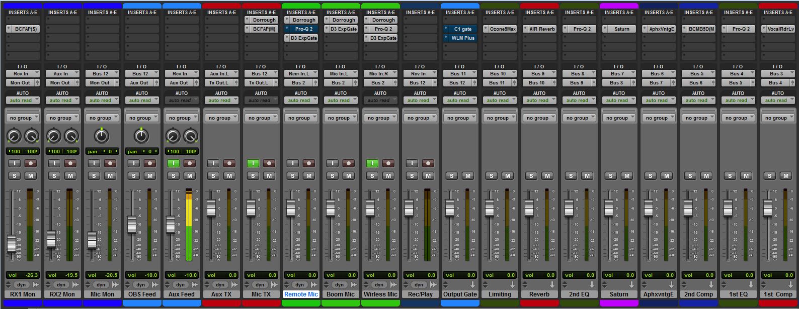
Using DAW software, one can process speech for optimum performance in ways that even PowerSDR cannot, whether that is for ESSB rag-chew, AM rag-chew, chasing DX, contest use, etc. Multiband compression, intelligent limiters, and an essentialy limitless list of other processing options offers endless possibilities to tweak voice signals. DAW software is typically so good that generally no processing is used in PowerSDR when using a DAW. Everything including the leveler is turned off, and the DAW is relied on to accomplish 100% of the desired speech processing. The only function that is non-defeatable in PowerSDR is the ALC.
Using Voicemeeter Banana, it is possible to fully integrate PowerSDR with many popular DAW programs in including Ardour, AudioMulch, Pro Tools and Sequoia, among others. The methodology for accomplishing this I have described in a separate paper, available here: ASIO & DAW Setup For PowerSDR.