WU2O piHPSDR Controller Unit
Updated 25 January 2017 (Originally
published September 2016)
This page was originally published in
September of 2016. Since then a lot has been learned, the software has
improved quite a bit, and built-in, local
audio capabilities have been added.
Why Build A Controller: The Vision
A piHPSDR controller is not something
I ever think of using for serious work. I
have a big, powerful computer with triple displays for that sort of
thing. The big computer has the necessary poop to run digital mode
software, loggers, and to
utilize all of the amazing powers of our radios. But the piHPSDR rig
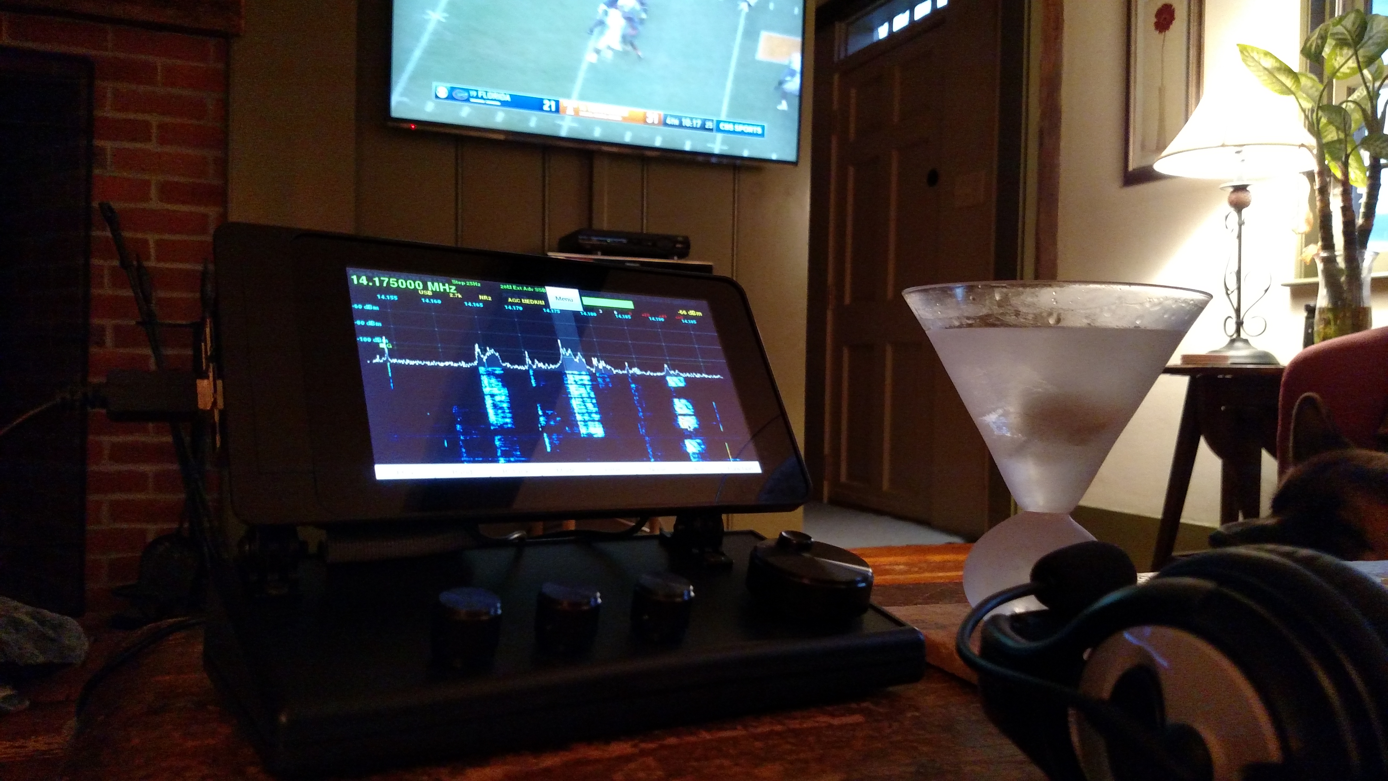
has enough power to make it easy to envision
sitting in my favorite easy chair, the little controller propped on the
side table, feet up, drinks and snacks handy, maybe a football game up
on the big screen, and be able to casually work some DX or rag chew.
Anyhow, that's my vision and I'm sticking to it, as is plainly evident
;-)
This vision is getting closer and closer to reality. In September
the controller only had the most vestigial capabilities, and executing
a QSO was very problematic. Now, as of late December, one can have
perfectly serviceable phone QSOs with it and operation is quite stable
and reliable. There is even a three band audio equalizer for receive
and transmit. While there is a lengthy list of things to take for
granted in PowerSDR that are still missing, most notably split, freely
adjustable passbands, VOX, leveler, compressor and, of course,
PureSignal, no doubt these features are coming down the road. As these
features arrive, transmit audio quality, the hallmark characteristic of
openHPSDR architecture radios, will continue to improve. It is my hope
that eventually people will have to ask me on the air whether I'm using
a piHPSDR controller or a full size PC. If you are reading this in,
say, June of 2017, certainly things will have changed dramatically by
then.
Do you want to build your own controller? I bet you do! Even in thick
client form, the entire idea
remains quite compelling. Not only is it
fun to use, it's a quick and easy build. It
requires mostly mechanical fabrication skills and a little Linux savvy.
Material costs hover in the $350 range with built-in audio, a far cry
from the $1200 Maestro. And the future promise of using the controller
in a client-server role is, of course, the Holy Grail.
John Melton's (GO0RX) recent work on
piHPSDR,
his
presentation
at the 2016 Friedrichshafen ham radio conference, and Apache Labs
announcement of a
piHPSDR Controller Unit, was sufficiently
intriguing to motivate me to make my own piHPSDR controller unit.
There is obviously tremendous interest in this sort of thing. Indeed,
one might even say there is a bit of "Maestro envy" in the openHPSDR
community. The Flex
Maestro
being, of course, a "knobified", stand-alone, thin client controller
for the Flex series of client-server architecture software defined
radios (SDRs). However, before anyone gets too excited, there are a few
things to remember:
- openHPSDR architecture is still in "thick client" form and
thereby requires a fast, reliable, low latency connection to the
radio hardware. You might get Wi-Fi to work, and you might not. You
definitely won't be taking this thing to a hotel room with you and
using it over the internet at this time.
- John is a "one man band" and the software is in a constant
state of evolution. Hence don't expect to find all the features of
PowerSDR with every
bell and whistle possible when riding the bleeding edge of development
with your home brew piHPSDR controller unit.
- The Pi 3 processor is by no means an i7. Again, this will
necessarily limit what this unit can do in thick client form. Someday,
when the openHPSDR architecture evolves to client-server form, then the
sky will be the limit, but that day is not today.
That said,
current CPU usage on the Pi 3 is only in the 25% range. Clearly there
is plenty of poop left to implement PureSignal and more, and the Pi 3
remains a surprisingly capable platform for SDR use, particularly with
the efficiency with which John's code runs.
Design Notes
In developing my design I wanted something clean, compact, simple to
build, inexpensive, and requiring no printed circuit card development.
Obviously the design needed to include the four rotary encoder
controls, as that is the
signature design element. However, I intentionally did not include the
eight hardware switches, as I did not find that the soft keys on the
touchscreen display take up too much room. In fact, it seemed that the
soft keys on the touch display were more ergonomically pleasing.
However, now that I've got some operating time under my belt with this
controller, I do often wish for a PTT button. Nevertheless, I am
holding off on installing one until such time as VOX becomes a feature
of the software. I suspect that will be sufficient. Besides, leaving
out the eight buttons saves a ton of fussy measuring, drilling,
wiring and whatnot. Just try to get those eight buttons aligned in a
perfectly straight row without some milling equipment--good luck!
Speaking of luck, I found that the dimensions of the Smarticase
Pi/touchscreen enclosure and a Hammond sloped instrument enclosure
matched exactly. It was like they were made for each other.
In terms of encoder selection, there are a great many to choose from. I
wanted them to be panel mounted, not printed circuit board mounted.
Cost was definitely a consideration, otherwise I would have selected
all optical encoders, as nothing feels like a really well made optical
encoder. However, only the tuning wheel got an optical encoder, the
remaining encoders are the very inexpensive Bournes units.
Knob selection was very important. Cheap knobs that don't fit would
ruin the entire aesthetic. The aluminum knobs specified are a bit
pricey, but they really make the design shine!
To simplify wiring, I chose from one of the many so-called Raspberry Pi
"cobbler" kits. These kits provide a nice little printed circuit board
and connector that make connecting to the Pi GPIO connector very easy.
In terms of power supply requirements, the Pi, display, USB audio
interfaces (see below) and whatnot draw only a total of 1.1A going full
blast while running piHPSDR. So the 2.5A wall wart
Raspberry Pi power supplies would seem to be OK with a good cable. I
suspect that most people experiencing problems are using USB cables
with 28AWG conductors in them. If you see a yellow lightning bolt on
the top right portion of your display, it means the Pi has detected an
under-voltage condition. Do a little research, and buy carefully. There
are many cables out there with 20AWG conductors in them and those will
work much better. I chose to go the overkill route since it is not very
expensive. Therefore a 10A supply from Adafruit with a barrel to
microUSB adapter was specified.
For storage, a 32GB SD card was a
no-brainer as storage is cheap, so no point in under-specifying that.
Finally, the design choices associated with obtaining local audio
output from the Pi were surprisingly complex. Initially I tried the
tip-ring-ring-sleeve (TRRS) audio/video connector output from the Pi.
Unfortunately, it turns out that the audio quality from this interface,
even when properly connected to an external amplifier, is quite poor,
with a bad noise floor. Apparently this is a known issue with this Pi
interface. Although some Pi's are OK in this respect, mine, like most,
was not. Therefore I chose to use an inexpensive USB audio interface. I
wanted good volume and spent some time researching various small
amplifier boards and speakers. To that end I chose a particular, 5V
powered, small amplifier board that got good reviews on eBay. I chose
the speakers more for looks than anything else! I wanted the speakers
to be on the top surface for best fidelity and volume and I did not
want to engineer speaker grills. So I chose a small speaker from Dayton
Audio that "looked good". As it happens, they also sound darn good as
well!
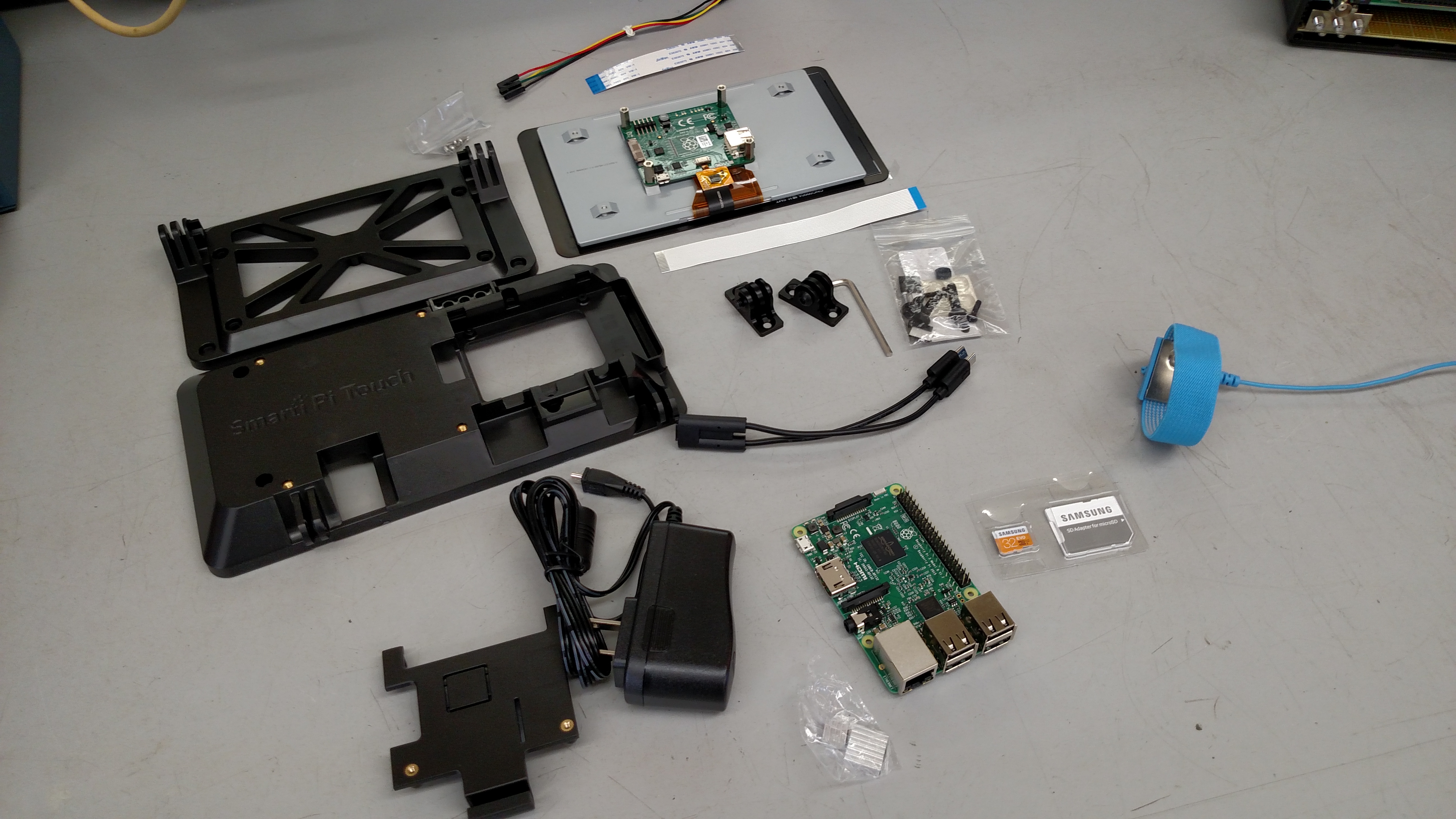
Material Requirements
The design that I implemented depends very strongly on the availability
of a particular Raspberry Pi 7" touchscreen housing from Smarticase. Of
all of the components on the bill of materials, that is the only one
that I would be worried about in terms of its continued availability.
The rest of the parts are "meat and potatoes" items from stable
suppliers.
| Item |
Manufacturer |
Mfg Part Number |
Supplier |
Supplier Part Number |
Qty |
Price Each |
| Touchscreen/Pi enclosure |
Smarticase |
SmartPi Touch w/microUSB
Y-cable |
See mfg. site |
SmartPi Touch |
1 |
$29.99 |
| Encoder enclosure |
Hammond |
1599HTSBK |
Mouser |
546-1599HTBSK |
1 |
$13.24 |
| #8x3/4" flathead machine
screws |
N/A |
N/A |
N/A |
N/A |
4 |
<$.25 |
| #8 flat washers |
N/A |
N/A |
N/A |
N/A |
4 |
<$.10 |
| #8 lock washers |
N/A |
N/A |
N/A |
N/A |
4 |
<$.10 |
| #8 nuts |
N/A |
N/A |
N/A |
N/A |
4 |
<$.10 |
| Processor |
Raspberry Pi |
Model 3 B |
Various |
Follow this link |
1 |
$35.70 |
| 7" touchscreen display |
Raspberry Pi |
7" Touchscreen LCD
Display |
Amazon |
Follow this link |
1 |
$69.99 |
| GPIO cable & breakout
board kit |
Nulsom |
RPi GPIO Cobber |
Amazon |
Follow
this link |
1 |
$8.95 |
| 10A 5V power supply |
Adafruit |
658 |
Adafruit |
658 |
1 |
$25.00 |
| MicroUSB to 2.1 barrel
adapter cable |
Adafruit |
2727 |
Adafruit |
2727
|
1 |
$1.95 |
| 32GB MicroSDHC card with
adapter |
Samsung |
MB-MP32DA/AM |
Amazon |
Follow
this link |
1 |
$11.50 |
| 24 PPR/24 detent encoder
w/switch |
Bournes |
PEC11R-4215F-S0024 |
Mouser |
652-PEC11R-4215F-S24 |
3 |
$1.63 |
| Small knob |
TE Connectivity |
KN770B1/4 |
Mouser |
506-KN700B1/4 |
3 |
$10.10 |
| 120 PPR/no detent optical
encoder |
Broadcom/Avago |
HRPG-ASCA-13C |
Mouser |
630-HRPG-ASCA-13C |
1 |
$30.90 |
| Large knob |
TE Connectivity |
KN1751BS1/4 |
Mouser |
506-KN1751BS1/4 |
1 |
$34.96 |
| Speaker |
Dayton Audio |
CE32A-8 |
Various |
N/A |
2 |
~$10.00 |
| USB Audio Sound Card
Adapter |
Sabrent |
AU-MMSA 2.1 |
Various |
N/A |
1 |
~$7.00 |
| Audio Amplifier Board |
uxcell |
PAM8403 |
Amazon |
Follow this link |
1 |
<$3.00 |
| 1/8" stereo mini phone
plug |
N/A |
N/A |
Various |
N/A |
1 |
<$1.00 |
| USB Left Angle A-to-A
Cable |
UCEC |
N/A |
Amazon |
Follow this link |
1 |
<$3.00 |
| Hookup wire (28 to 22AWG
will work) |
N/A |
N/A |
N/A |
N/A |
AR |
|
| Solder |
N/A |
N/A |
N/A |
N/A |
AR |
|
| Heat shrink tubing
(various diameters) |
N/A |
N/A |
N/A |
N/A |
AR |
|
| 3M high bond double sided
tape |
N/A |
N/A |
N/A |
N/A |
AR |
|
| Black RTV adhesive |
N/A |
N/A |
N/A |
N/A |
AR |
|
*AR=as required
Construction Details
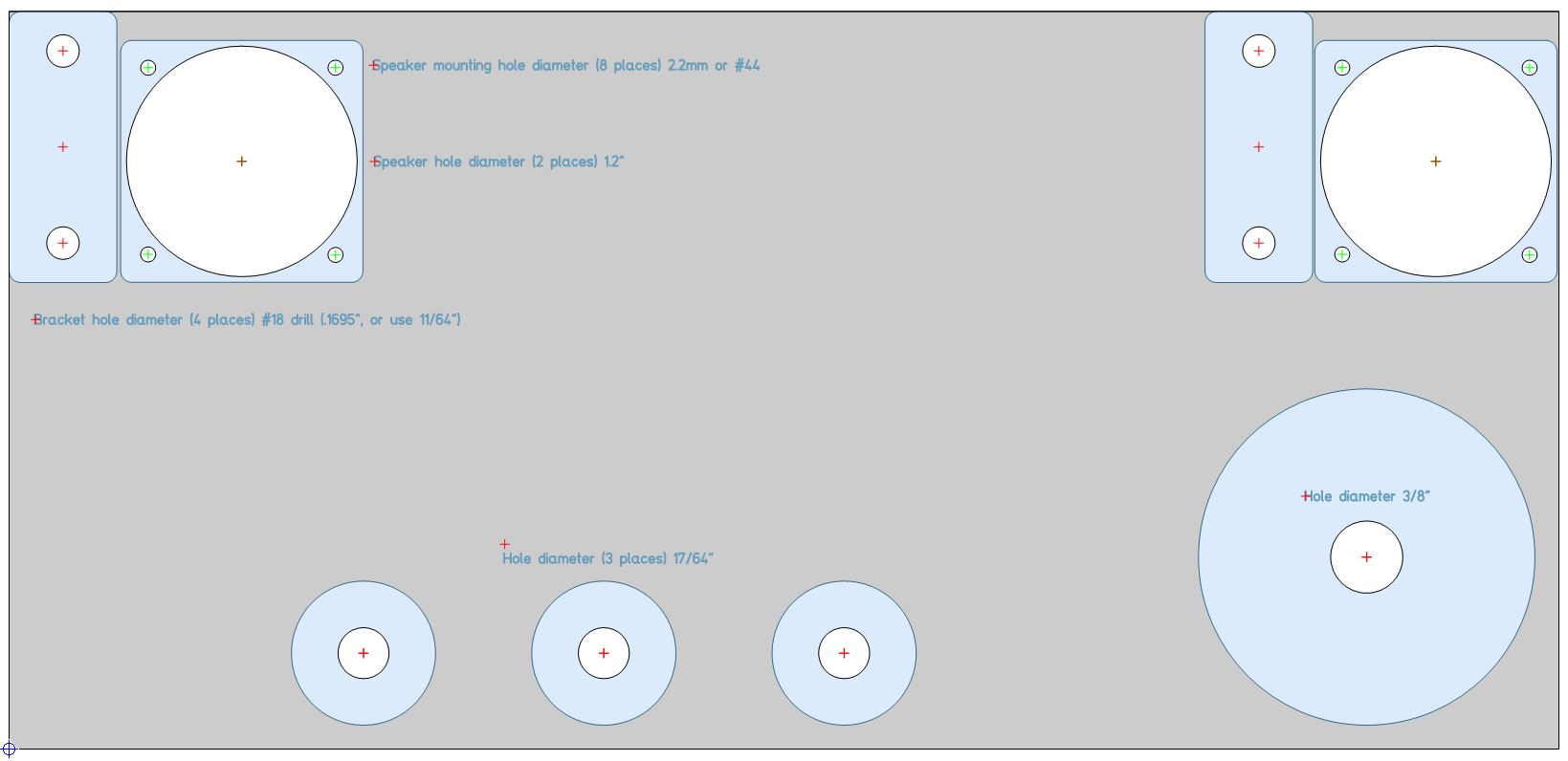
Drilling the Top Panel
Download and print the
drilling
template.
Print at 100%. Cut out the template and tape it to the top surface of
the Hammond enclosure. If printed at 100% it should match the top inlay
surface of the enclosure. Mark the reference points with a scratch awl
or other pointed tool. Drill holes sized in accordance with the
drilling template. The plastic on the Hammond enclosure is very soft. I
had best results by drilling at very low speeds and by drilling the
holes in steps, starting with a 1/16" pilot hole and moving up through
some intermediate size drills before drilling at the required final
diameter. How accurately these holes are made makes the difference
between a good looking product and a not so good looking product. For
the speaker openings I used a large step drill bit.
Undercut the Mounting Boss
The rear left mounting boss on the top panel will interfere with the
fastener in the corner that attaches the Smarticase hinge. Use a Dremel
or similar tool to carefully machine away the mounting boss plastic
such that a nut and washer can be placed in that area.
Attach the Smarticase Hinges to the
Top Panel
Not much to say here. Screws, washers, nuts. Just make sure the hinges
are oriented so that the hinge fasteners insert from the left and right
so that they are easy to access. Test fit the Smarticase after the
hinges are mounted, just to see if any adjustments are in order. I
managed to find these really nice, black oxide coated, socket flathead
screws at the local hardware store. They are sexy!
Hand Fit the Speakers Into the Top
Panel
This can be very fussy work to make it look good, depending on how you
decide to do it. In my case I did not want to engineer or fabricate a
set of speaker grills. Therefore I chose to front mount the speakers
into the enclosure. To accomplish this required some delicate hand
filing of the enclosure and fitting of the speakers. In retrospect it
might have been easier to fabricate those speaker grills, and I have
since obtained some metal grill material that I may use in another
version. Nevertheless, the speakers do fit quite nicely next to the
display hinges, and are reasonably well protected in those spots. You
will need to find some 2mm fasteners and hardware to fit through the
speaker mounting holes. I actually found some at my friendly local
hardware store, however I may order some black oxide coated hardware
off of the internet just to make it look a bit sexier.
After fitting the speakers, remove them and lay them aside as you will
not want to install them until you have soldered the leads to them.
Also, by assembling the speakers last they are less likely to be
damaged.
 Assemble the Touchscreen and Pi Into
the Smarticase
Assemble the Touchscreen and Pi Into
the Smarticase
For now don't use the supplied screws to secure the Pi, just let the
door secure the Pi and, optionally, add those screws when all is done.
The reason for this is that otherwise the Pi can't be lifted out to
insert the SD card. And don't use the jumper wires to power the
touchscreen. Instead plan to use the microUSB Y-cable that comes with
the Smarticase kit to power the Pi and the touchscreen.
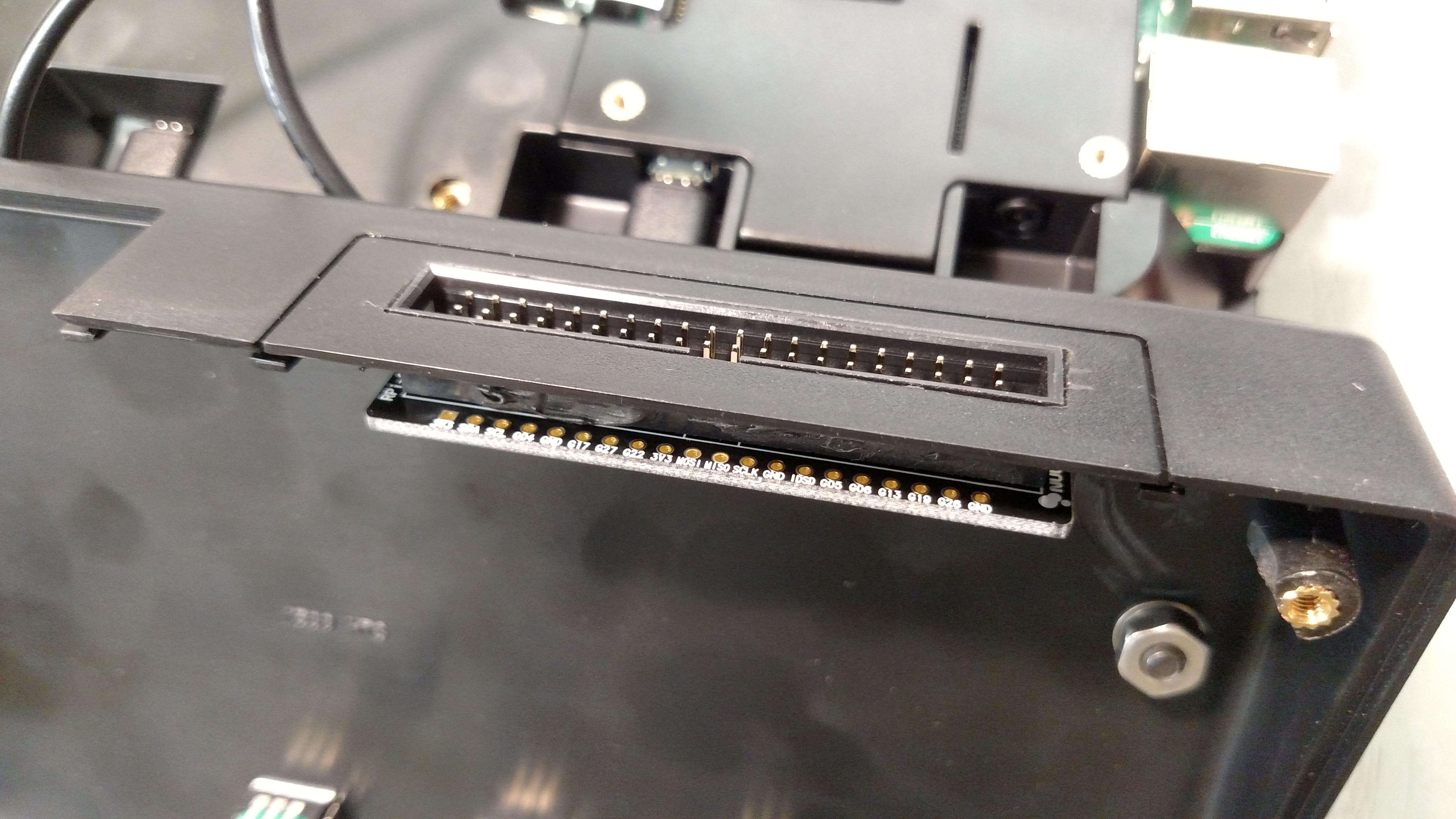
 Solder the Cobbler Board to the
Cobbler Connector
Solder the Cobbler Board to the
Cobbler Connector
Temporarily assemble the Pi, GPIO cable, cobbler connector panel and
cobbler board. Check the mechanical orientation and fit of everything.
Power up the Pi and, with a meter, check that 5V, 3.3V and ground are
in showing up on the labeled places on the board. This will help avoid
the very annoying mistake of soldering on the board in the
wrong orientation. Once you are 100% happy with the orientation of the
board, solder all of the pins to the connector.

I am so embarrassed I took that photo before cleaning the flux off!
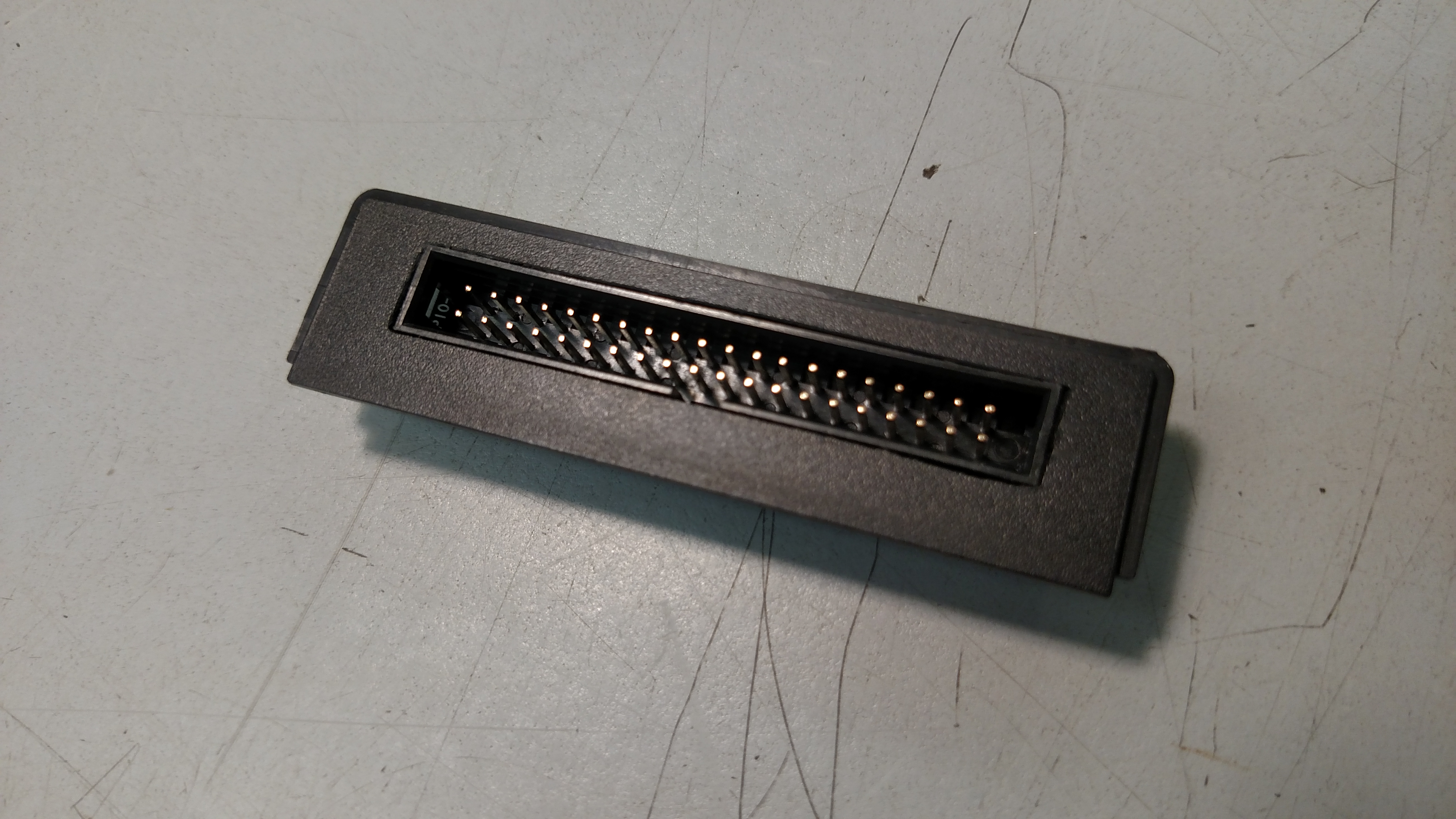
Fabricate the Cobbler Kit Connector
Panel
The Hammond enclosure comes with these nice little removable panels on
the back. I mounted the cobbler kit connector into the left side panel,
aligned with where the GPIO connector is on the Pi when it's mounted in
the Smarticase enclosure. This is probably the most difficult part. I
wanted mine to be as good as I could get it, so, after drilling a
length
of 1/4" holes to make the beginnings of a rectangular hole, I spent a
lot of time hand filing that hole to be rectangular. Most people will
probably just go
to town with a Dremel. Your choice! Once the hole is made, lay the
exterior surface of the panel down on a flat surface, drop the cobbler
kit connector into the panel hole with the key oriented down towards
the bottom edge of the panel and glue it together with some RTV. Do not
get RTV in the keying area or on the pins. Let it dry overnight. You
will be tempted to fuss with it that day, but that will just result in
the assembly being damaged.
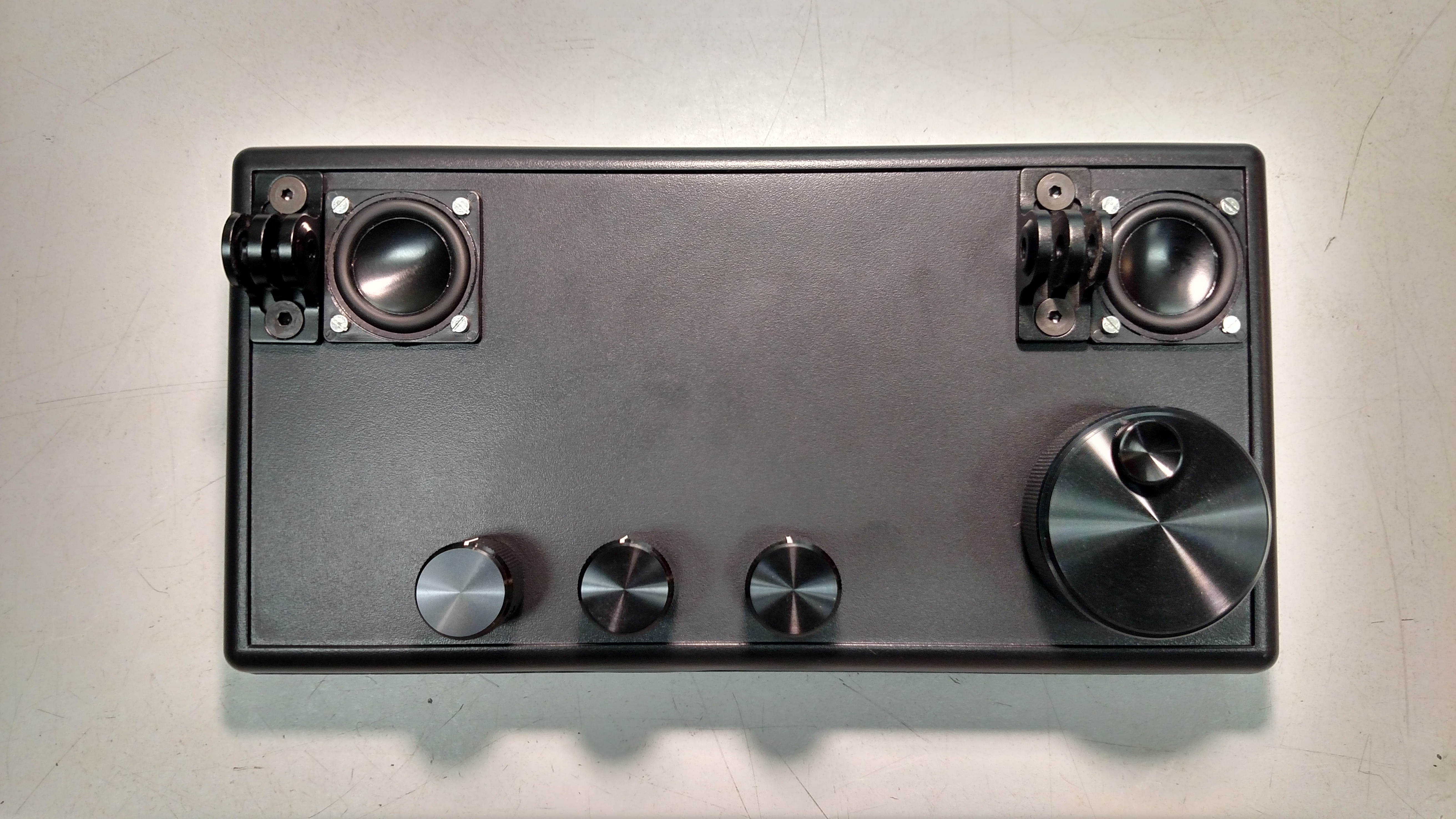
Assemble the Encoders into the Enclosure
Align them as you prefer for doing the wiring. You can follow my
example shown below if you desire. The mounting nuts do not require a
lot of force. These are small devices made out of inexpensive pot
metal, so go easy on them. Indeed, the Bournes encoders are, dare I say
it, cheap, and easily damaged. Again, go easy.
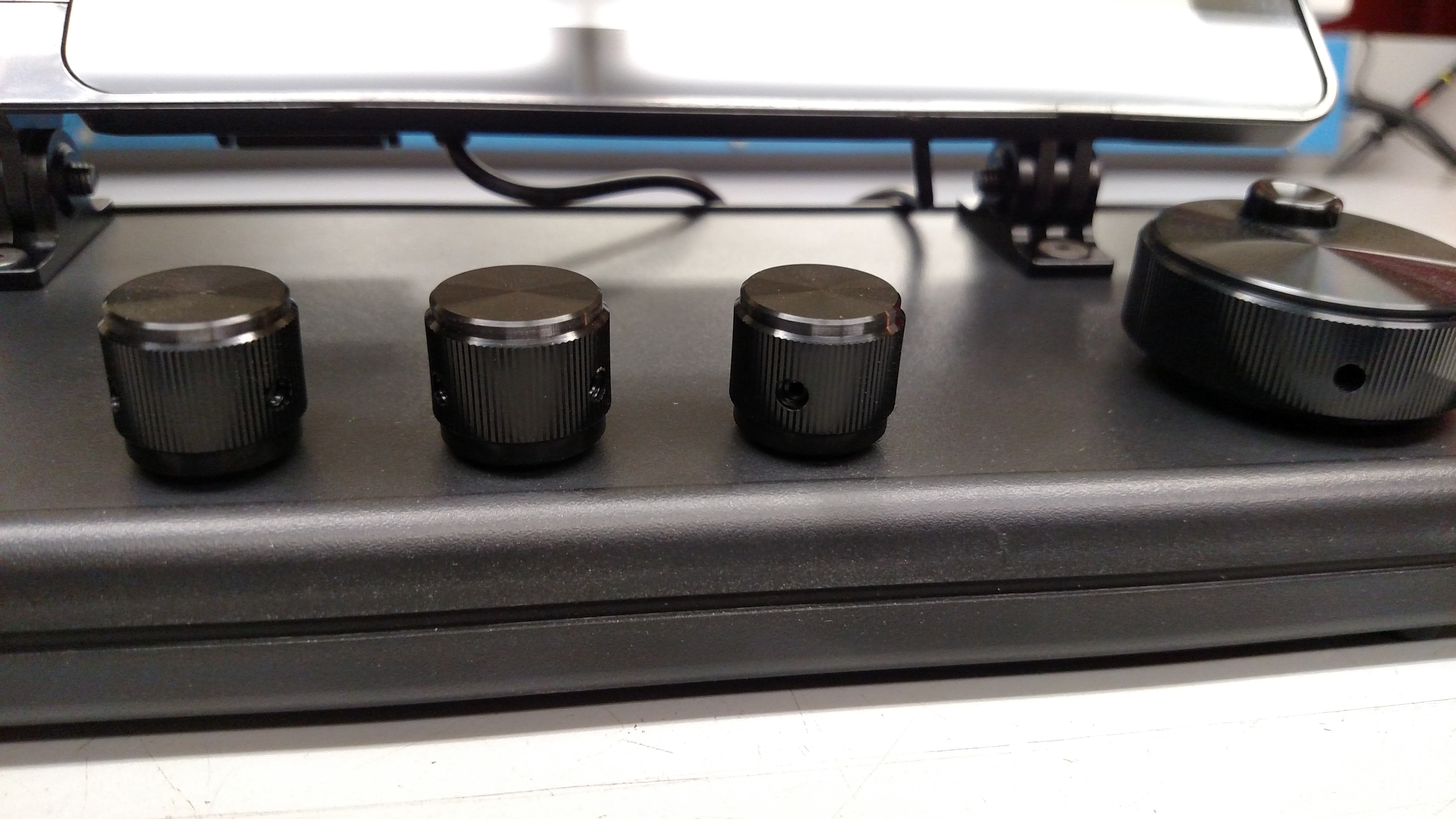
Assemble the Knobs onto the Encoders
You will need a 1/16" Allen wrench. On the small knobs, align one of
the set screws with the flat on the shaft, tighten, loosen just a
little, and let the knob fall until the set screw is resting on the D
section floor. This will ensure that all knobs are the same height and
have enough clearance to the enclosure surface. On the large knob just
let the knob fall all the way to the bottom of the shaft. Make certain
the knobs are not sitting so low they drag on the enclosure or, on the
Bournes encoders, hit the enclosure when pressing down to activate the
momentary switch action. Tighten all of the set screws, of course.
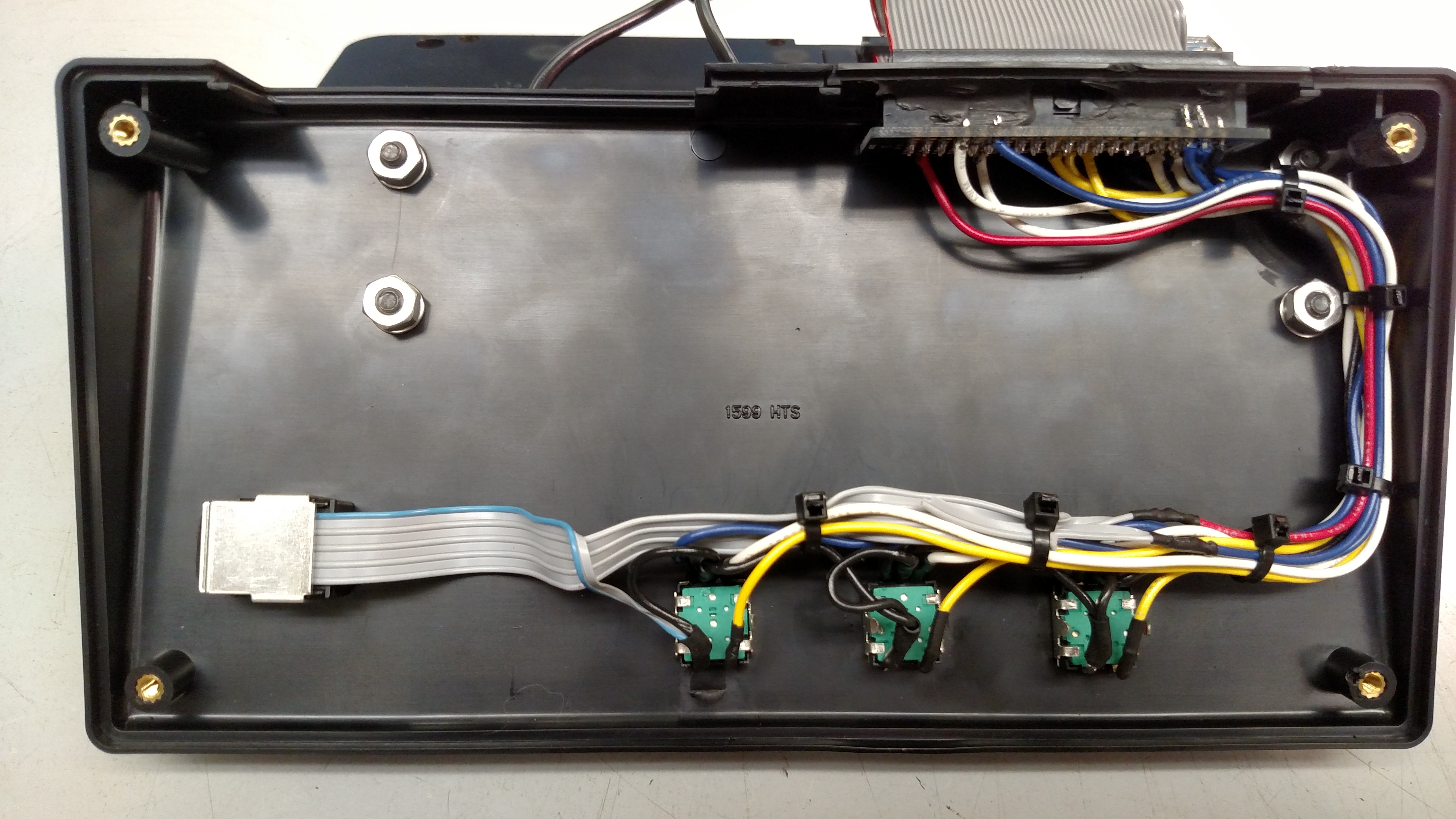
Wire the Encoders to the Cobbler Board
Refer to the manufacturer's data sheets, available from Mouser, for the
pinouts of the encoders. I simply daisy chained a single ground wire
all the way over to the cobbler connector. Both ground pins on the
encoders need to be wired. If you accidentally reverse the A and B
lines it's no big deal, you can reprogram that in the piHPSDR software.
Only the Avago optical encoder needs a 5V connection.
The photo below shows the unit wiring before I added the speakers,
which is handy for clarity's sake. The wires are routed around the edge
of the assembly so that the
center area is left open for the audio components.
Be very careful with the soldering iron. If it touches the Hammond case
the case will melt instantly. Similarly, if you use shrink tubing and a
heat gun, go easy with the heat on the case. If you are very paranoid,
you could actually assemble the encoders into something temporary so
that they have the same orientation, like a scrap piece of plastic or
cardboard, wire them, then transfer the entire assembly back into the
case. In fact, if I build another one, that is exactly what I am going
to do.
Wiring is as shown in the table below.
| FROM
|
TO
|
| ENCODER
|
PIN
|
GPIO
CONNECTOR PIN # |
GPIO
SIGNAL |
| VFO |
+5V |
4 |
+5V |
| VFO |
A |
11 |
GPIO 17 |
| VFO |
B |
12 |
GPIO 18 |
| VFO |
GND |
Note 1 |
GND |
| AF |
A |
37 |
GPIO 26 |
| AF |
B |
38 |
GPIO 20 |
| AF |
C |
Note 1 |
GND |
| AF |
1 |
Note 1 |
GND |
| AF |
2 |
22 |
GPIO 25 |
| AGC |
A |
40 |
GPIO 21 |
| AGC |
B |
7 |
GPIO 4 |
| AGC |
C |
Note 1 |
GND |
| AGC |
1 |
Note 1 |
GND |
| AGC |
2 |
26 |
GPIO 7 |
| RF |
A |
35 |
GPIO 19 |
| RF |
B |
36 |
GPIO 16 |
| RF |
C |
Note 1 |
GND |
| RF |
1 |
Note 1 |
GND |
| RF |
2 |
24 |
GPIO 8 |
Note 1: ground wires were daisy
chained from encoder pin to encoder pin and terminated
on GPIO connector pin #39 (GND). Other GPIO ground pins include 6, 9,
14, 20, 25, 30 and 34.
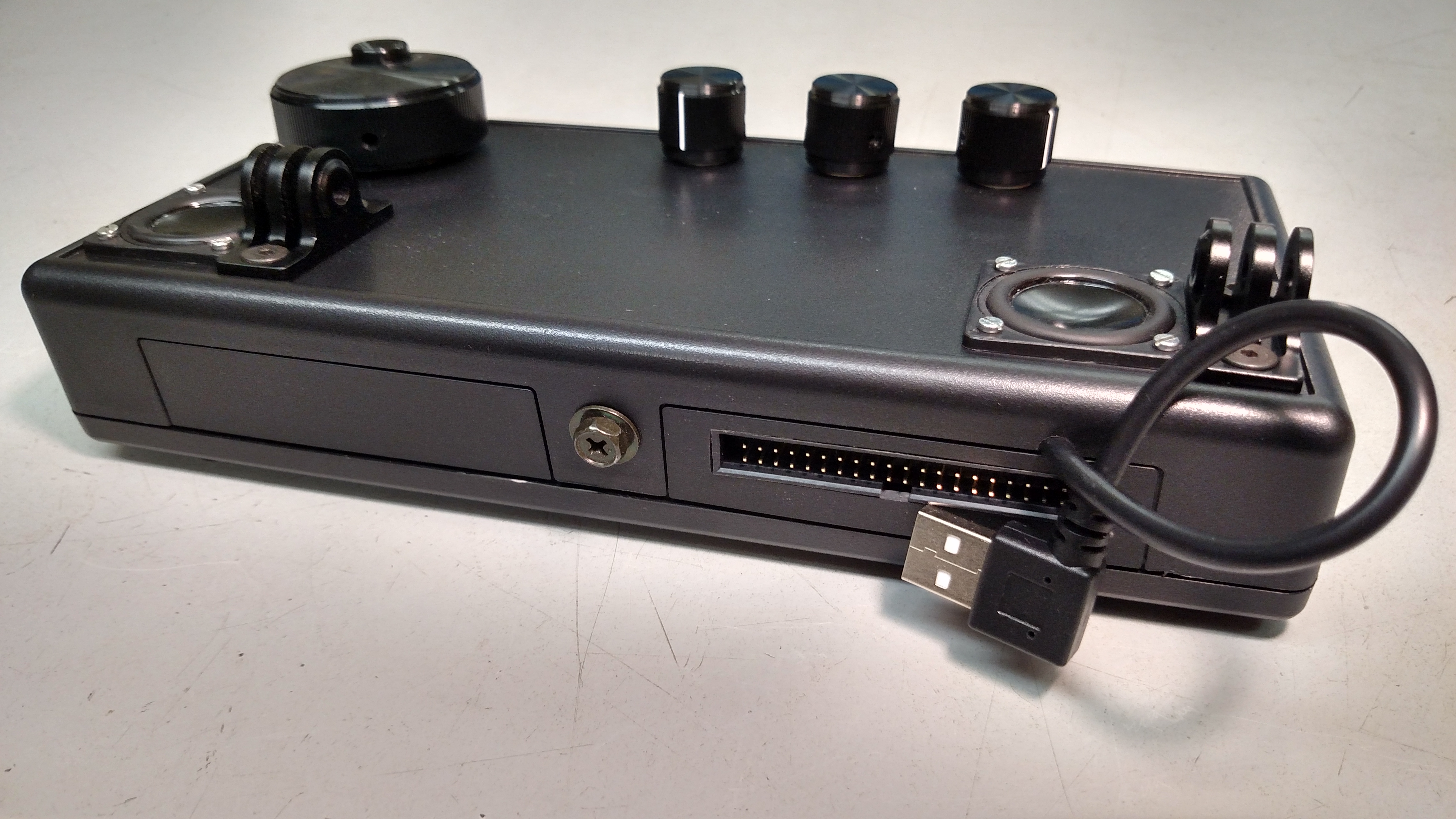
Assemble the Audio Components
Make a small notch in the case as shown to allow passage of the
left-handed, right-angle USB extender cable. The left-hand nature of
the connector is important so that it has a fair lead out from the USB
connector on the side of the Pi. If you make the notch just a little
small, it will hold the cable securely and not allow it to be pulled
out of the enclosure. Test fit the display as required to ensure you
have enough cable to reach the USB connector and for the display to be
able to be angled over its full range. (Note the screw on the back as a
future ground connection point--so far I have not needed to ground the
unit, though).
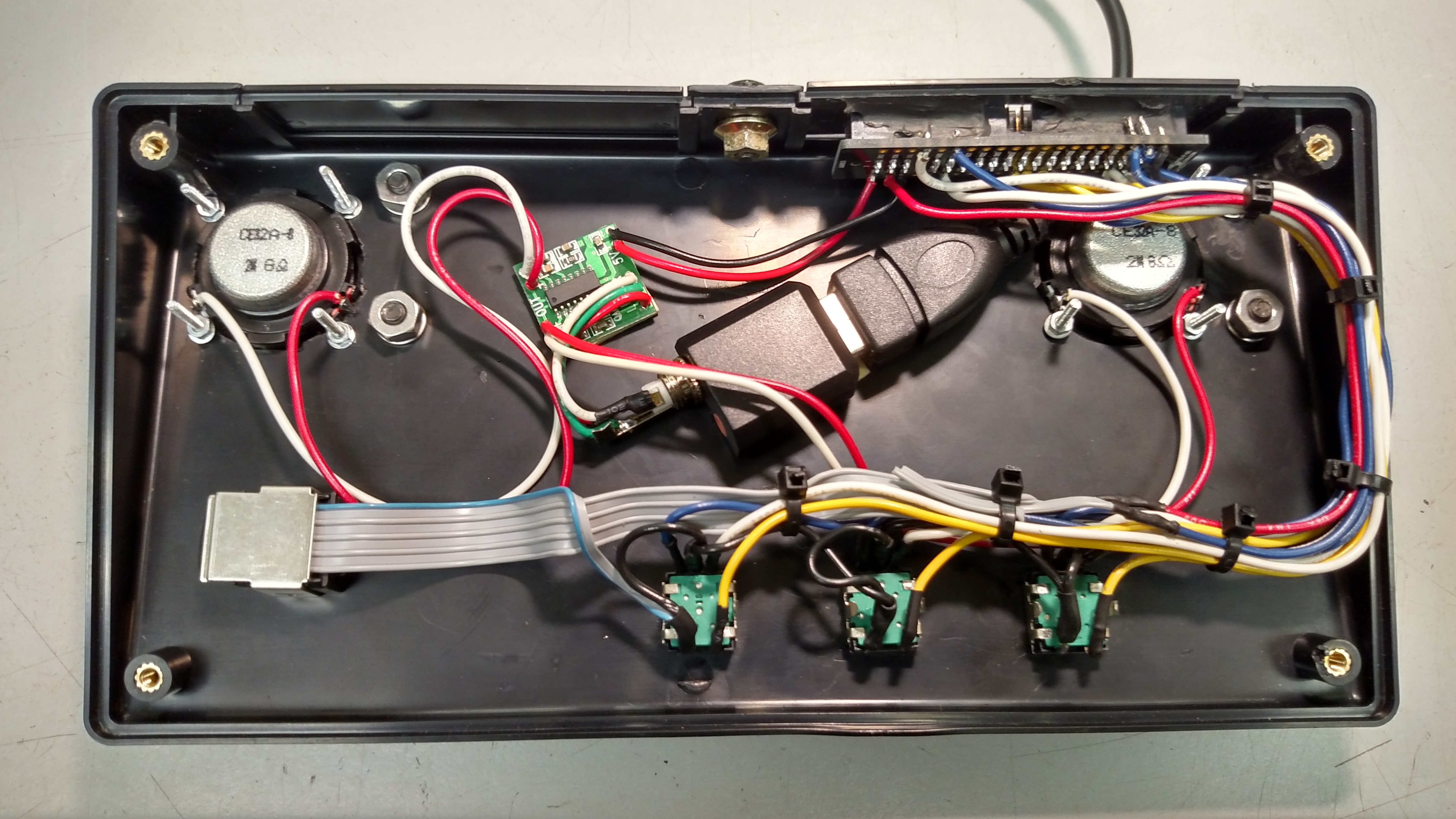
With the USB extender cable arranged as shown, secure it and the
Sabrent USB audio interface with some 3M double-sided, high bond tape
(or equivalent).
Solder speaker, power and input wires to the audio amplifier board.
Again, it is recommended to do this outside the enclosure on the bench
as the Hammond enclosure is quite heat sensitive. Also solder the 1/8"
mini stereo phone plug to the inputs wires: tip is left, ring is right
and shield is ground.
You can pull the cobbler board assembly out and away from the enclosure
to solder the 5V and ground wires from the audio amplifier to it.
Plug the stereo phone plug into the green jack on the Sabrent USB audio
interface. Secure the audio amplifier board into the enclosure with
some 3M double-sided, high bond tape (or equivalent).
Finally, solder the speaker wires to the speakers before mounting them
to avoid soldering iron heat damage to the enclosure, then assemble the
speakers into the enclosure. When soldering the speaker wires pay
attention to achieving the same polarity on both speakers. This way the
speakers will operate in phase with each other for best sound quality.
You might also, optionally, consider provisioning an 1/8" mini mono
jack on the rear of the enclosure, connected to the microphone input on
the Sabrent USB audio adapter. This way you could plug in a wired
microphone to use locally. I chose to forgo that approach for now, as I
prefer to use a USB headset when actually having a QSO.
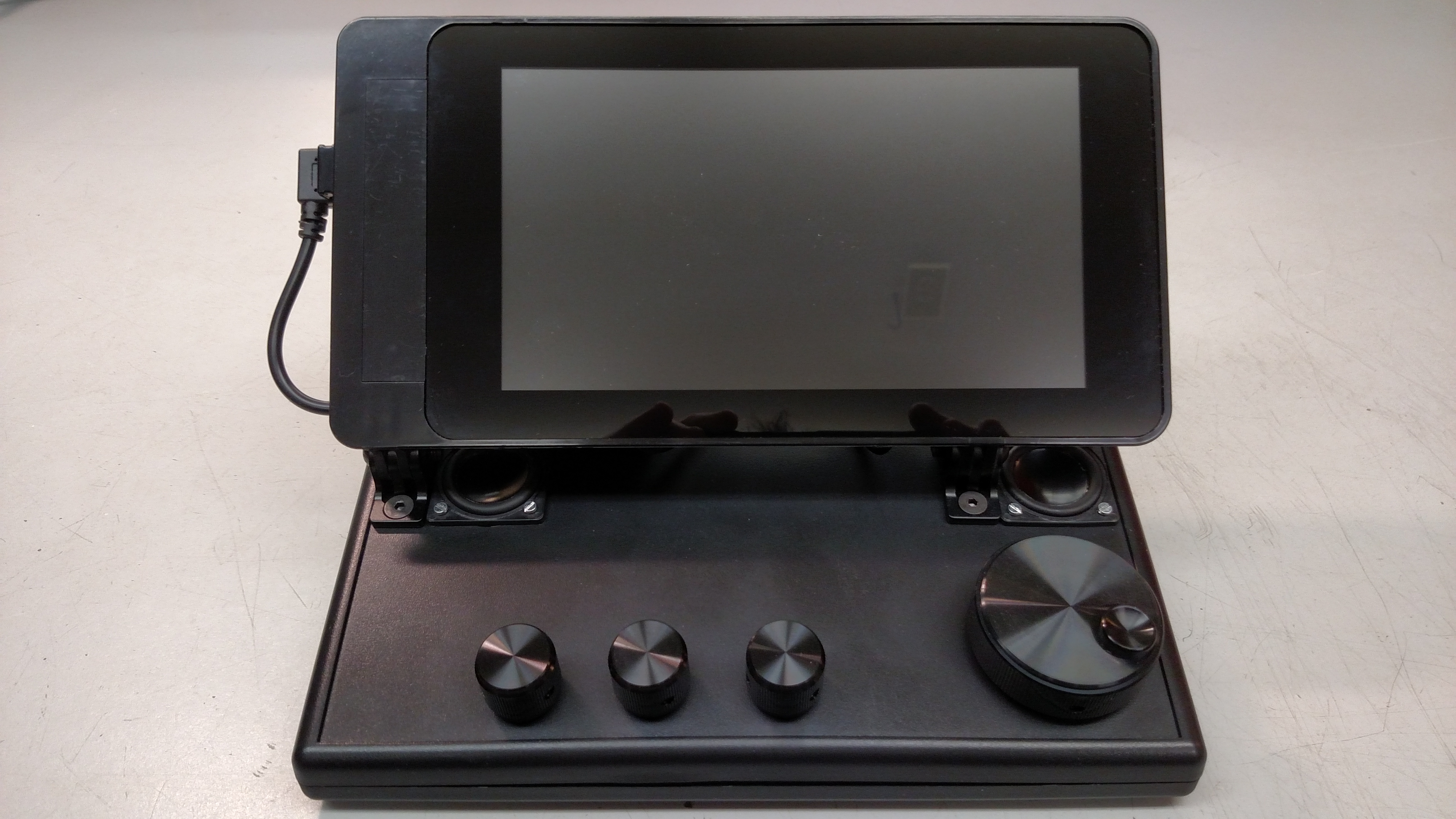
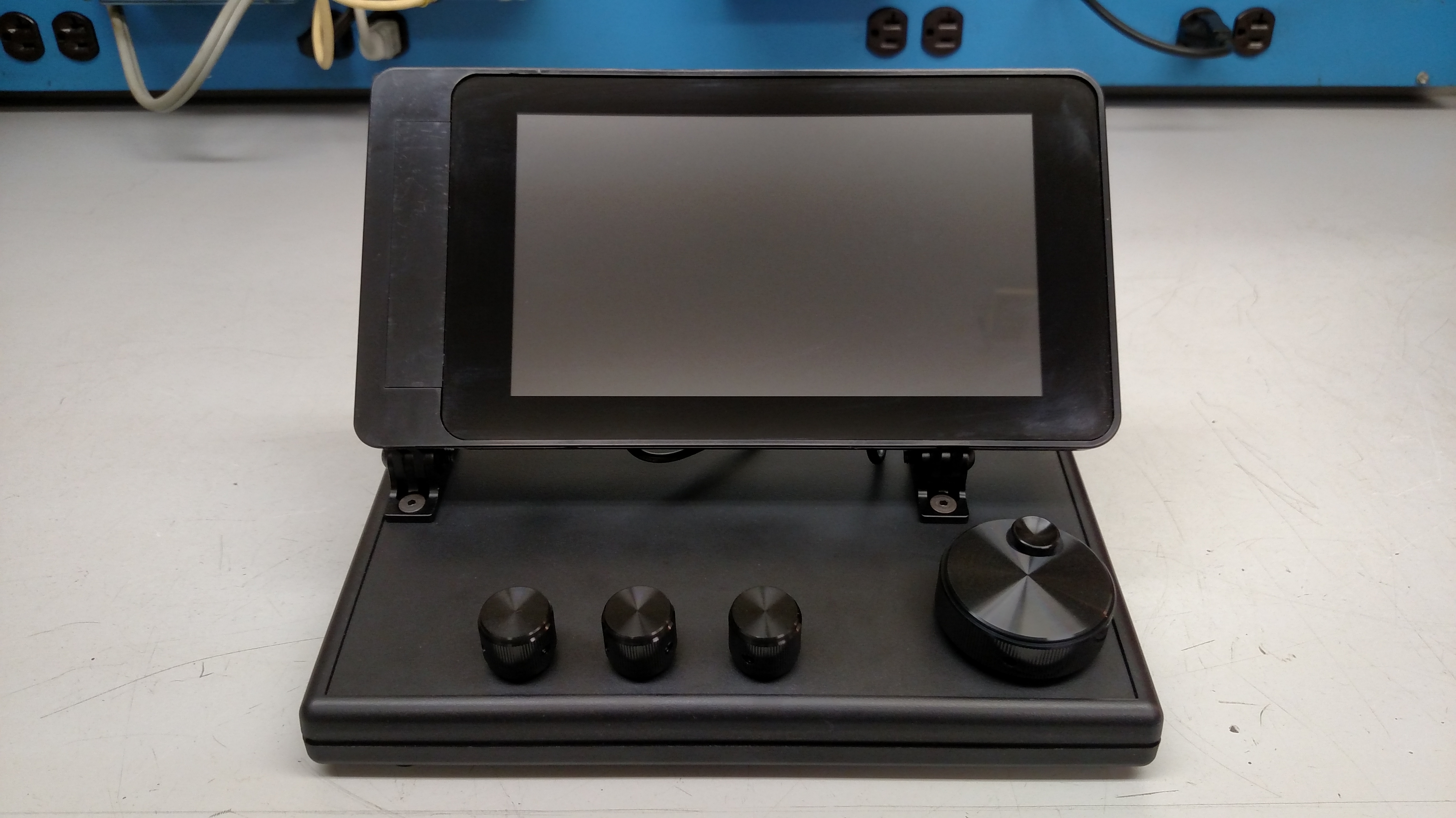
Assemble the Smarticase onto the Hinges
Oh boy, now it's starting to look cool! You might consider modifying
the GPIO cable to be shorter. It is possible to disassemble and reuse
the IDC connector at one end. Carefully pry it off, then measure and
trim the ribbon cable. Be sure to leave enough cable so that the
display can hinge over its full range of motion. Then reassemble the
IDC connector, with the correct orientation of course, at the new end
of the cable. A bench vice makes a handy press for IDC connector
assembly. If you don't have a vice to squeeze it in I'm not sure I'd
try this. IDC connectors and ribbon cable are cheap and you can always
get some additional material and simply make a whole new cable later.
Don't forget to plug in the USB cable to the audio interface, too.
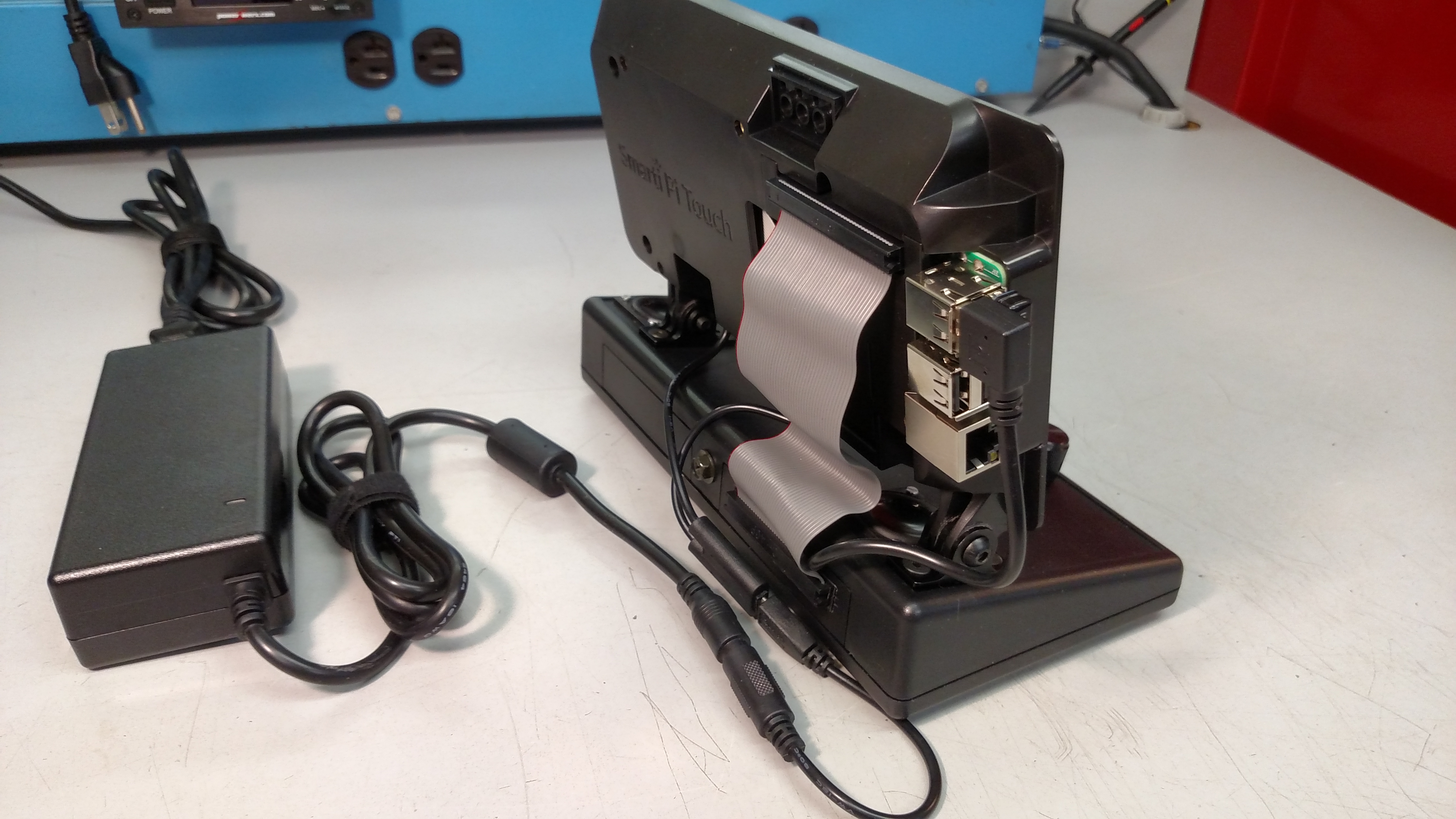
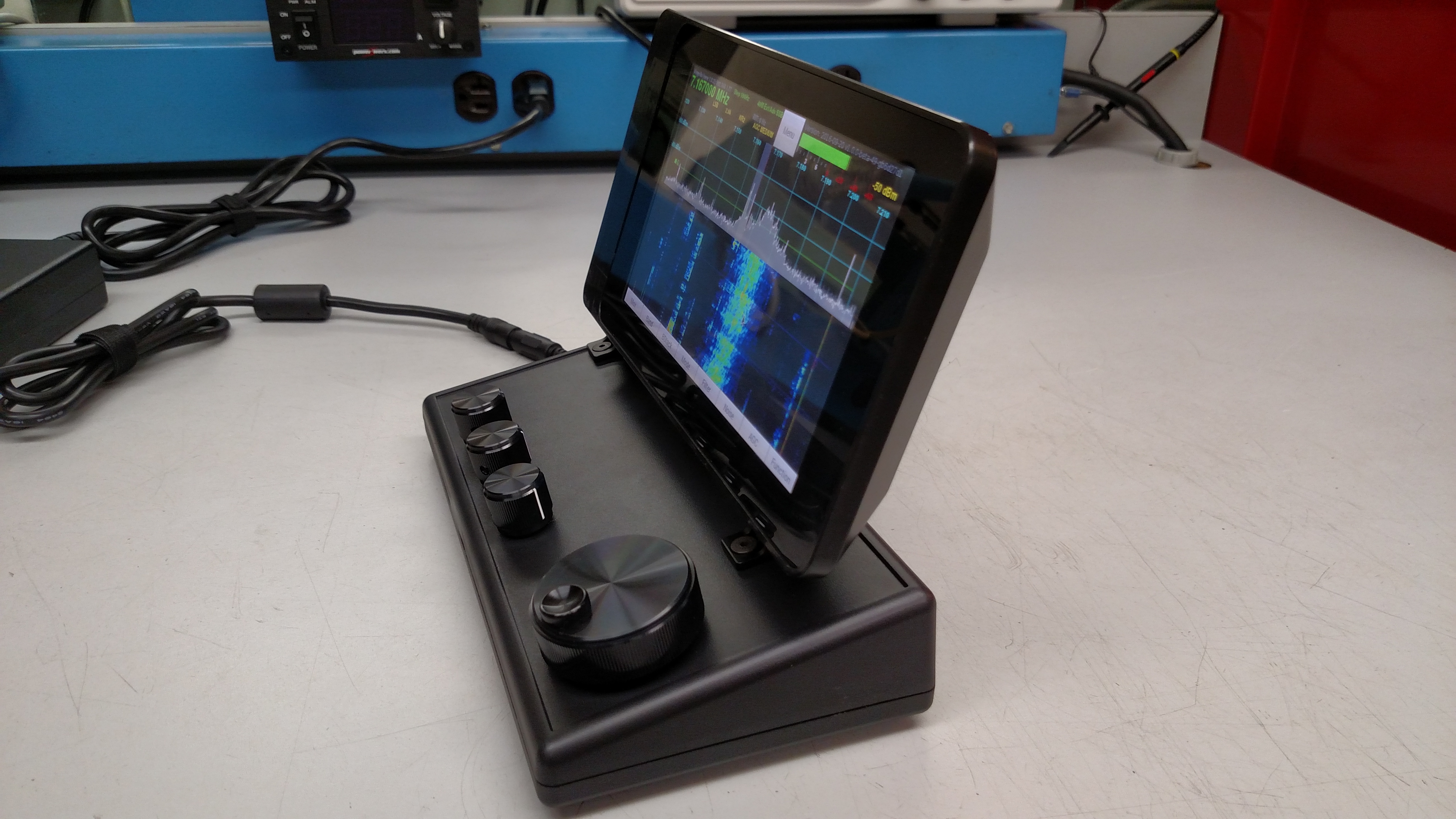
While not the
most flattering photographic angle, nevertheless in this photo you can
also see the Adafruit 10A 5V power supply and
2.1mm barrel to microUSB adapter cable. This attaches to the micro-USB
Y-cable to power the touchscreen and the Pi. Ten amps is plenty
for USB headsets, audio amplifiers, 802.11ac Wi-Fi dongles, and
whatever else might be added in the future for, as mentioned above, the
whole kit is drawing only about 1.1A as is.
Build, Install and Configure the pi
Operating System
Get the Pi and touchscreen running. There are plenty of websites to
hold your hand here. If you are not a Linux jockey, be prepared to
hack--er, I mean learn! Google and Youtube are your friends. However, I
will suggest a few hints and recommendations:
- An HDMI display is not needed. The latest version of Raspbian
will find the touchscreen right away if the touchscreen is properly
attached.
- Install MobaXterm on your PC first. That way you can just SSH in
for configuration and don't need to bother with attaching a mouse or
keyboard. Google "using MobaXterm with Raspberry Pi".
- Use straight Raspbian, don't bother with NOOBS.
Install piHPSDR
Follow John's instructions in the installation document precisely. It
can be found at
https://github.com/g0orx/pihpsdr/tree/master/release/documentation.
Configure piHPSDR GPIO Settings
When piHPSDR is started, it will first be necessary to press the button
to configure the GPIO settings. The three Bournes encoders will require
the pull-up
to be turned on, but not the Avago optical encoder. If any A and B
settings need to be swapped, this is
where it can be done. Be aware that the numbers shown are the GPIO
signal numbers, not the connector pin numbers.
This is also where the knobs can be rearranged. If you decide you want
to re-order the knobs on the front panel, just change the numbers here
to get what you want.
Test the Encoders and Encoder Switches
With piHPSDR up, running and connected to a radio, twist the knobs and
see what happens. As of December 2016, the AF knob will adjust the
audio volume and pressing its momentary switch will lock and unlock the
VFO. The AGC knob obviously adjusts the AGC level, pressing its
momentary switch will change the knob to RIT. The RF knob adjusts RF
drive and right now the switch doesn't seem to do anything.
If something isn't working right then things will have to be debugged!
Most likely there is a wire misplaced on the cobbler board.
Assemble the Bottom onto the Hammond
Enclosure
A few encoder pins may need to be bent or a few wires moved for
clearance. I put the supplied stick-on feet next to the fastener holes,
not over them, since I expect I will want to modify the unit in the
future.
If the entire assembly feels a little unbalanced, a few small lead
weights glued inside the front of the bottom part of the housing with
RTV will give it a little extra heft.
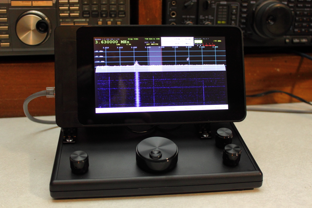
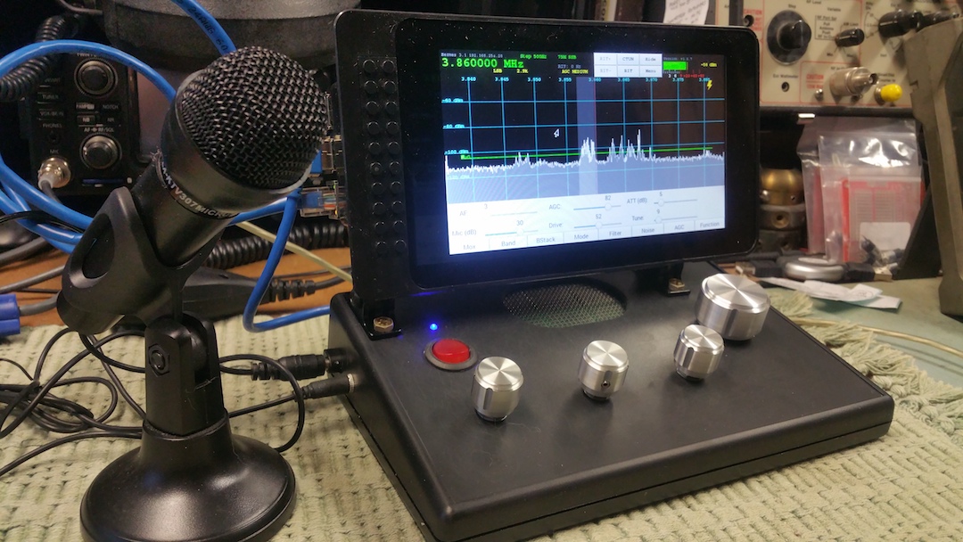
The Finished Result, Local Audio, and
Some Operating Tips
So there you have it, a nice piHPSDR controller with built-in, good
quality, local audio capability. Having the built-in USB audio
interface does not preclude the use of additional USB audio devices,
although currently piHPSDR will only let you use one at a time.

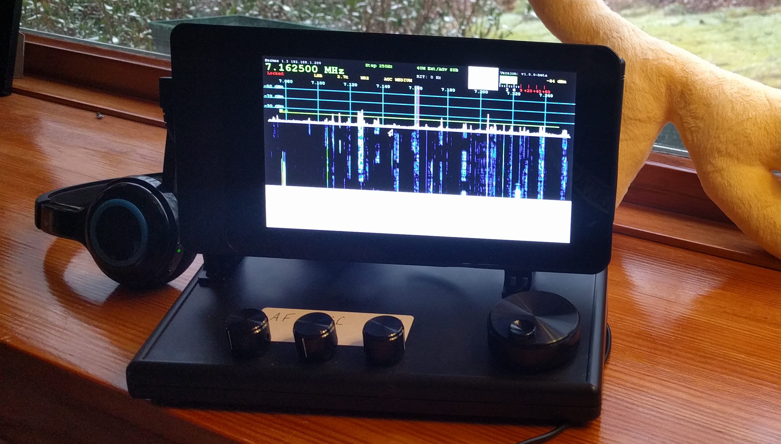
In the photo above you can see a Logitech H-800 wireless headset.
This headset works quite well with the Pi by means of its 2.4GHz
wireless USB dongle adapter. Although this headset is also Bluetooth
capable, Bluetooth on Linux, and Raspbian in particular, is not quite
ready for prime time! There is also a less expensive H-600 version. And
of course you can use essentially any wired USB headset on the market.
I've had very good luck, and very good signal reports, with a Microsoft
Lifechat LX-3000.
Local Audio Setup
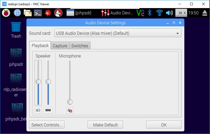
In Raspbian, click on the Start Menu (the raspberry icon in the upper
left),
then Preferences, then Audio Device Settings. Choose the "USB Audio
Device" and make it the default. This will now allow the Pi to produce
all of its sounds through the Sabrent audio adapter and the Dayton
Audio speakers. Hit the "Select Controls" button, enable all controls,
and then set the Playback Speaker levels to 50% to start. Play some
Youtube videos or something to test your work.
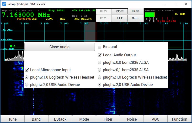
When using piHPSDR, obviously you
must select the audio interfaces you
wish to use for receive and transmit in Menu > Audio. Be sure to
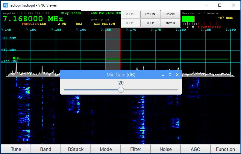
check the "Local" boxes as appropriate. I have found that with every
USB audio device I have tried the microphone gain wants to be at 20dB.
Even though this results in quite a bit of ALC indication, 20dB mic
gain has obtained the best on air signal reports. Obviously this will
change as John implements more audio processing such as a compressor,
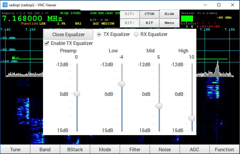
or a leveler, etc. I have also found that the USB audio sources
have benefited from a pronounced upward tilt in the equalization curve.
Watch your spectrum on the panadapter as you transmit and, as a
starting place, try to even out the energy content across the transmit
passband. As of December 2016, your transmit passband will be made
equal to the receive passband (filter) selected. The passband limits
are currently hardcoded, you can see what they are here:
https://github.com/g0orx/pihpsdr/blob/master/filter.c.
Finally, a word about latency. As of December 2016, latency in piHPSDR
is quite high. I have not measured it precisely, but it appears to be
on the order of 500mS. Using a Logitech H-800 wireless headset makes
this worse, as the 2.4GHz link of the headset adds another few hundred
milliseconds of latency itself. Certainly this can be expected to
improve as the code evolves.
Operating Tips
The number one thing that should be done before operating is to
calibrate the PA gain settings in piHPSDR. Without this being done it
can very difficult to obtain the desired performance from the radio
using piHPSDR. Be sure to go to Menu > PA and perform this
calibration. Use a dummy load, of course.
The method I recommend is to go into Tune mode and adjust Tune Drive to
be the value you will most normally operate at. If that is a barefoot
100W, set drive to 100. If that is 30W to drive an amplifier, then set
drive to 30. This way the calibration will be most accurate at this
drive level. With the drive set to your most used, nominal value, make
the adjustments in the PA Gain menu as required to obtain an RF output
power level that matches the commanded drive level.
Great Stuff: Other People's Work
Rick, N9HLL, and his interpretation of the project, with his own unique
encoder layout. Great work, Rick!
Doug, K3DAK, has built a version that uses 12VDC power and some
other neat touches. You can see many more detailed photos on how he
constructed it at his
imgur page.
Mike, K0JTA, went with silver knobs, a single large speaker, and very
cleverly used some printed circuit board material as a speaker grill.
He's also got a power switch, power LED, and brought out the microphone
input to his internal USB audio interface. You can read more about
Mike's build at his web site,
http://s3com.net/pihpsdr/page2.html.
If you have built a piHPSDR controller using my mechanical design, then
I'd love to receive a photo from you that I could add to this web page
to show off your work. As Rick did, no doubt many of you will have
slightly different arrangements of the knobs, etc., and it would be
great to show other ideas on control placement within the context of
the basic layout.
Future Projects: 802.11ac Wi-Fi and
Battery Power
The ultimate goal is to make
this piHPSDR controller completely wireless and portable. This should
be
doable. Using a 48KHz sampling rate, I can obtain good receive
performance, and transmit with an occasional garble, over an 802.11n
Wi-Fi connection. Testing with
iPerf3
finds my 802.11n connection capable of 6Mbytes/s, while the wired
100BASE-T connection is capable of 12Mbyte/s. Given others have been
successful in achieving greater than 12Mbyte/s on a Pi using 802.11ac,
I am confident I can use 802.11ac Wi-Fi to run the controller. To that
end I
have a D-Link DWA-171 802.11ac USB Wi-Fi adapter on order. This adapter
requires the installation of driver software to work, it will not work
with Raspbian out of the box.
I also have a 15000mA USB battery pack capable of sourcing 2A and am
waiting for delivery of
some 20AWG USB cables to test this battery pack with. If this
is successful then my piHPSDR controller will have achieved total
portability. More to follow!