Introduction
With all due respect to Apache Labs, the
mechanical and, in particular, the thermal design of the 100 and 200
series radios leave a lot to be desired. Certainly Apache was quite
successful at bringing them in at a price point that made them very
attractive to the openHPSDR software defined radio community. And the
openHPSDR architecture has so much going for it that certain foibles can
be somewhat overlooked. Nevertheless, even at a cost substantially less
than an equivalent Flex radio, when you are paying in excess of $2K you
sort of expect the radio to stay cool.
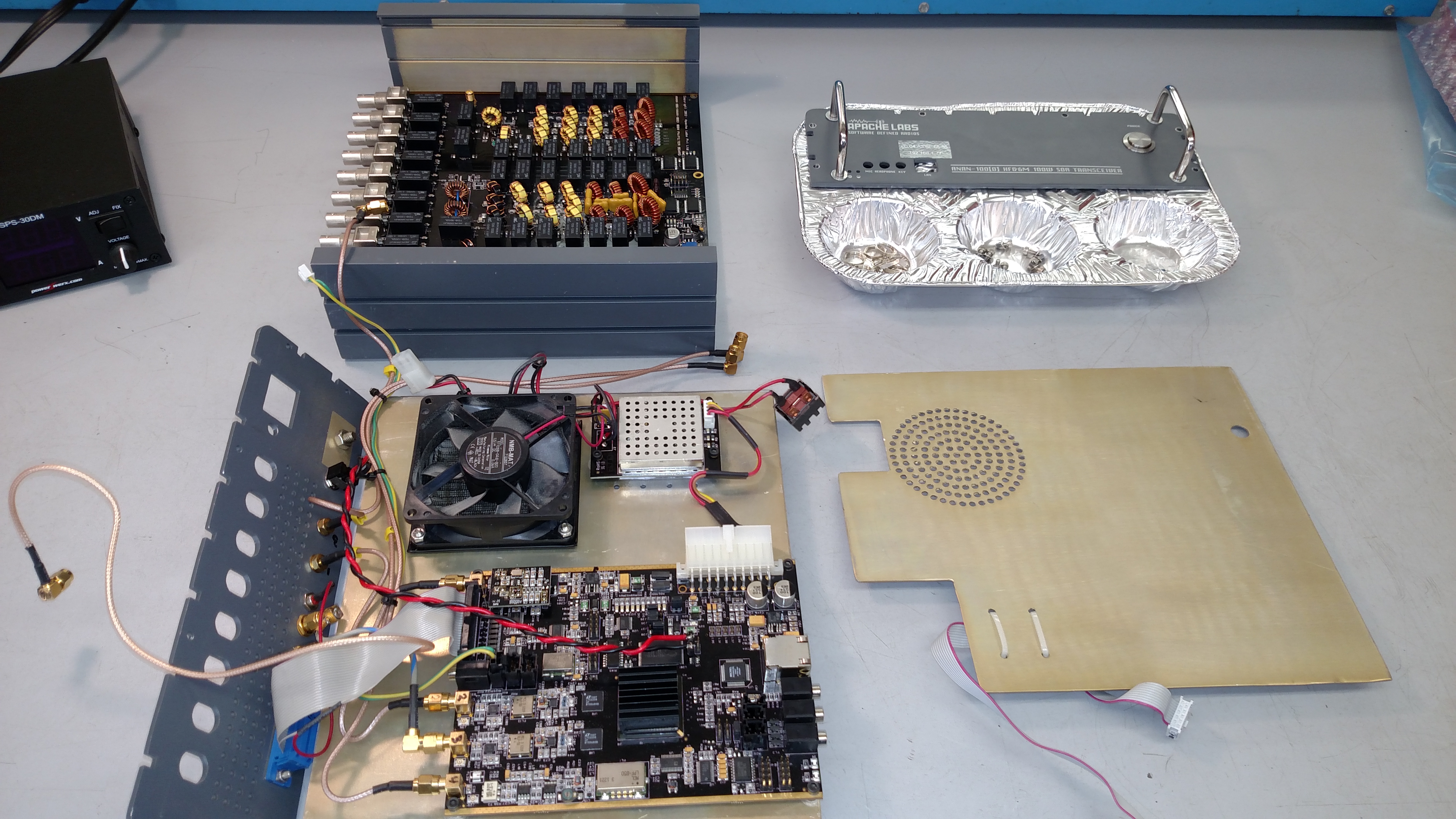
The basic problem is that there is no significant airflow either inside or outside of the radio. Internally, the fan blows directly into a major impedance, which is the central shield plate. I believe that early in the development of the radio there was no shield plate in the design. This allowed the fan to blow almost directly onto the RF FETs. However, it would appear that the shield plate was added due to some internal RF crosstalk issues. It is now a major impediment to cooling. With the shield plate in place, the fan pressurizes the bottom section and the air in that section effectively remains stagnant and does little to cool either the switching power supply or the SDR CCA. This stagnant air escapes through some holes in the shield plate into the upper section of the radio. Unfortunately, most of the air that does flow into the upper section of the radio doesn't flow over the PA/RF CCA, instead being short-circuited right out of the exhaust holes in the rear panel, which are in close proximity to the holes in the shield plate.
Externally, the heavy extruded housing is an effective heatsink for the four RF FETs that are mounted to its internal surface. However, using only passive convection, the extruded housing gets exceedingly hot during higher power operation. As a result, the 100 and 200 series radios are officially specified to provide continuous duty at only 30W maximum RF output.
External Cooling Makes a Huge Difference!
The single best thing you can do for your radio is both ridiculously simple and extremely effective, and that is to blow some air over the housing in the area where the RF FETs are mounted to it as a heatsink. It doesn't even take a lot of air, just a little will do, and you may be amazed at the substantial drop in the temperature of the radio.
Alex, DD5ZZ, made some fantastic time-lapse videos that show just how effective this is, and we are all indebted to him for this. Time compression is 25:1 with the original data being taken at 1 frame/sec.
In this first video, Alex is running FT8 for over an hour at 30W of drive:
In that video please notice that the temperature of each spot rises between 21 and 25 degrees, depending on the spot. In other words thermal rise is relatively even across the entire top surface of the chassis/heatsink. At the hottest spot the peak temperature got up to about 55C. Using the hottest spot we see that a 25 degree rise in temperature divided by the output power level of the radio, 30W, gives a figure of merit for thermal rise of .83 deg. C/W.
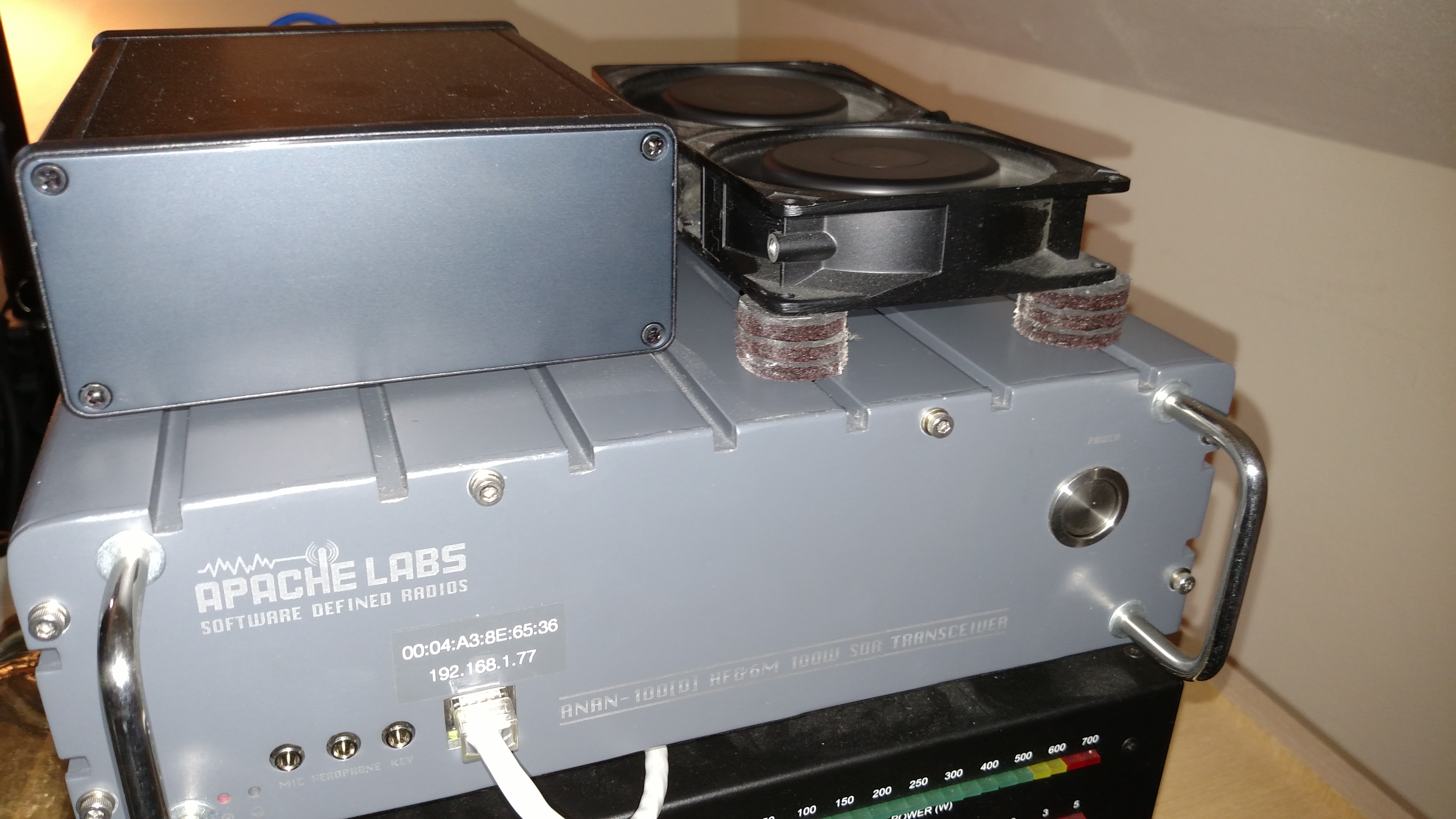
In Alex's second video, operating
conditions are exactly the same, however now Alex has placed a small fan
on top of the radio over the hot spot:
As can be seen from the second video,
this tiny little fan made a huge change in the temperature rise
of all of the spots, and now they only rise 12 to 13 degrees, which is half
of what they were without the little fan. Peak temperature now only gets
up to 43. Thermal rise is now only .43 deg. C/W.
So what's all this about thermal rise in
terms of deg. C/W? The really great thing about knowing the thermal rise
in terms of deg. C/W is that thermal performance of a given cooling
arrangement generally tends to be very linear and therefore one can
predict pretty accurately what temperatures will be obtained at any
power setting, assuming identical transmit duty cycle, of course.
Alex tests this concept in his third
video by increasing the RF output power level to 50W. Assuming a thermal
rise figure of .43 deg. C/W then we should expect to see a peak
temperature of about 21.5 degrees over the starting temperature. In the
video the starting temperature of the hottest spot is about 24 degrees,
thus the final temperature should be 24 + 21.5, or 44.5 degrees C.
Sure enough, the final temperature was
almost exactly as predicted, just a little bit higher at 46 deg, for a
thermal rise of .44 deg. C/W. Close enough!
So what does this all mean?
So what does this all mean?
First, a little air flow over the
outside of the chassis in the right spot makes a huge difference.
Active convection cooling is far better than passive convection
cooling.
Assuming a nominal room temperature of
25C, the fan-equipped chassis demonstrates a 0.44 deg. C/W rise. That
means at 70W the hot spot will only get up to 55C. At 100W it will only
get up to 68C.
Second, with a small fan you now have a radio capable of 100W at some respectably high duty cycles.
To be totally fair, there is also a thermal rise between the outside of the chassis and the case of the RF power FETs. What that is exactly I don't know. However it is unlikely to be very high, as the case of the FET is fastened by a socket-head cap screw directly to the underside of the chassis, with a little bit of thermal grease on the interface. I won't bore you with the calculations, but if you look at the data sheet of the Mitsubishi RD100HHF1 RF power FET, with the radio at 100W the maximum allowable FET case temperature is 132.5C. That means even at a chassis temperature of 68C the FET is running at almost a 50% de-rate in terms of maximum temperature.
External Cooling Modifications
I reached into my junkbox and found a couple of 120VAC muffin fans that I used to use to cool a home entertainment center cabinet. They are very quiet fans and move a modest amount of air. I wired them up, attached some stick-on foam feet, and arranged them so that the air blew down onto the top of the housing. Easy day!
Internal Cooling Modifications
It was probably a fool's errand, since air doesn't really move around inside the radio anyway. However, I happened to have the radio apart for other work, so I decided to upgrade the fan in the radio to one with higher performance. Fans of this nature are inexpensive, after all.
As it happens, the stock -B20 fan is the lowest performer in the NMB-MAT 3110SB series according to the datasheet, and it certainly does little more than maybe stir the air around inside the case a bit. However, it is very quiet, which was no doubt a major design driver when Apache was designing these radios.
There are plenty of other fans on that same datasheet with the exact same dimensions and much better performance, at the expense of very slightly higher power consumption and a little more noise. Since my PC fan is ten times louder than everything else in the studio, I wasn't really worried about noise. Looking at what Digi-Key and Mouser had in stock at the time, I chose the -B59 variant. This isn't on the datasheet, but it appears to be essentially a slightly more powerful version of the -50 variant.
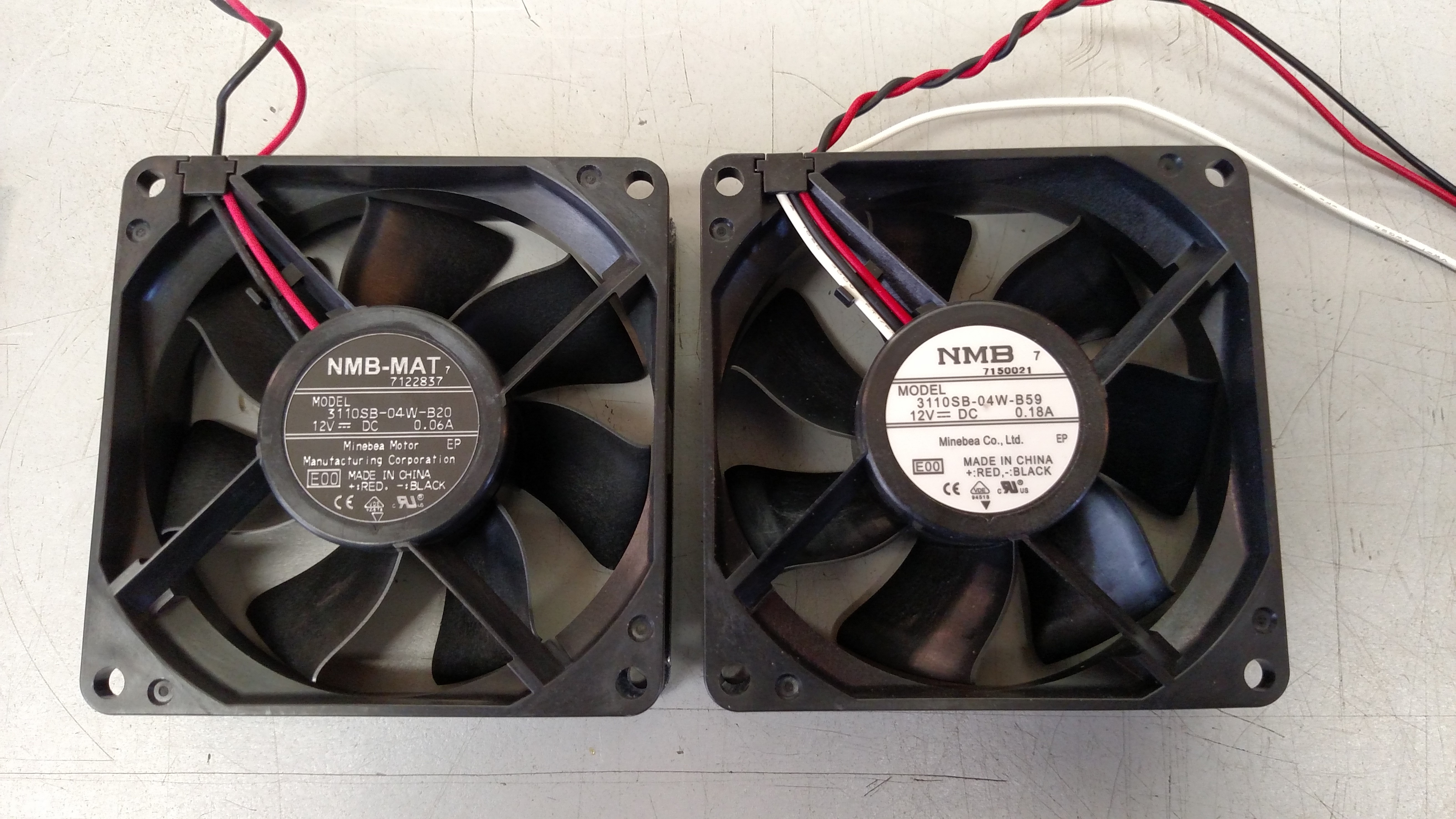
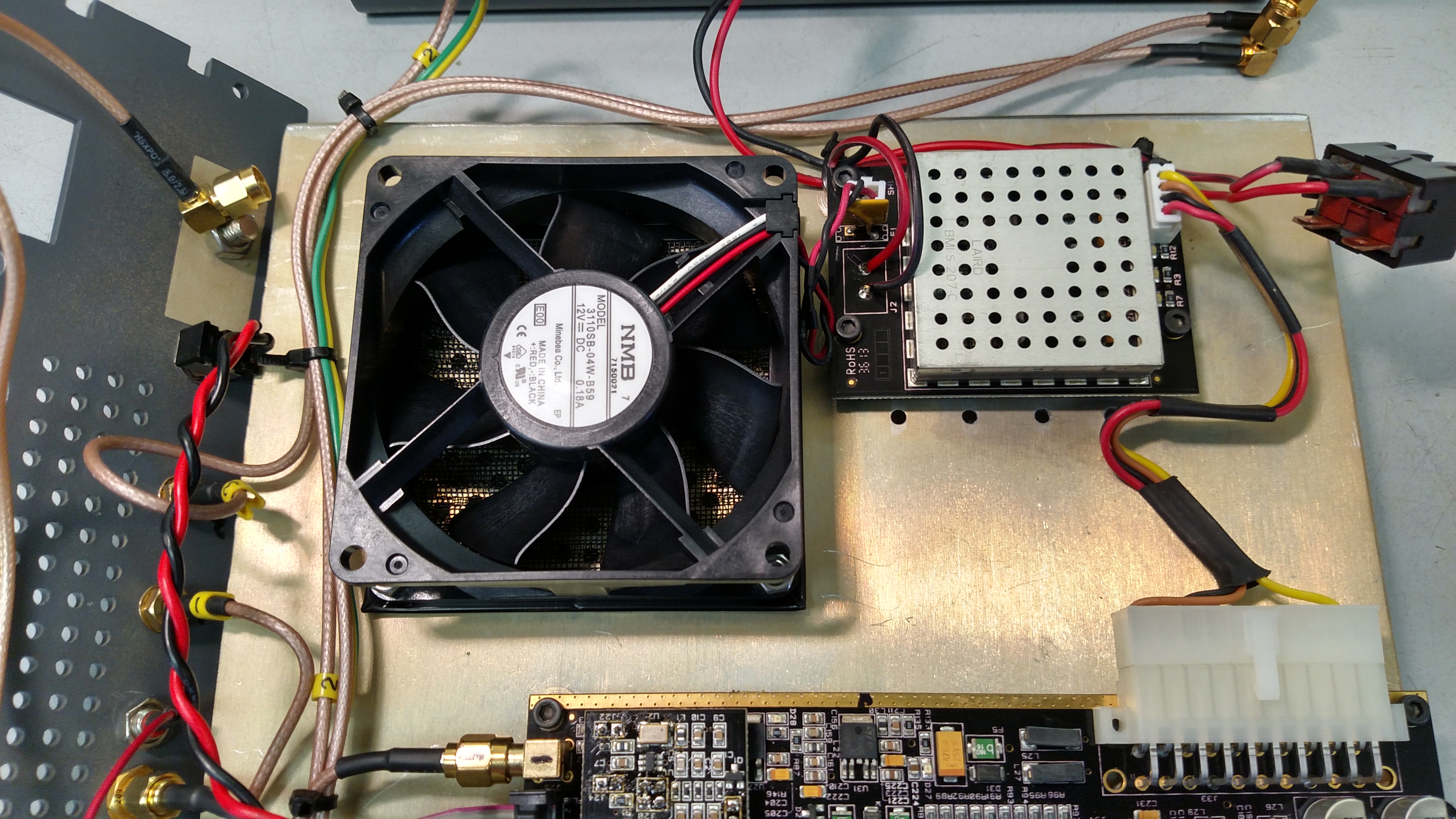
Compared to the -B20, the -B59 has half again the CFM rating, and at twice the static pressure. Not including getting the radio apart, installing it was simplicity itself. It drops right in with the same hardware, and one merely has to cut the stock fan connector off and reattach it to the new fan.
Someday I may rebuild the radio in a proper rack mounted enclosure with much better cooling. Until then putting the external fans on top has made a very big difference, and the up-rated internal fan certainly isn't hurting. I have thought about redesigning the center shield plate to move the internal air flow around more properly, but at that point moving the entire radio into a new chassis is probably a better bet.
Second, with a small fan you now have a radio capable of 100W at some respectably high duty cycles.
To be totally fair, there is also a thermal rise between the outside of the chassis and the case of the RF power FETs. What that is exactly I don't know. However it is unlikely to be very high, as the case of the FET is fastened by a socket-head cap screw directly to the underside of the chassis, with a little bit of thermal grease on the interface. I won't bore you with the calculations, but if you look at the data sheet of the Mitsubishi RD100HHF1 RF power FET, with the radio at 100W the maximum allowable FET case temperature is 132.5C. That means even at a chassis temperature of 68C the FET is running at almost a 50% de-rate in terms of maximum temperature.
External Cooling Modifications
I reached into my junkbox and found a couple of 120VAC muffin fans that I used to use to cool a home entertainment center cabinet. They are very quiet fans and move a modest amount of air. I wired them up, attached some stick-on foam feet, and arranged them so that the air blew down onto the top of the housing. Easy day!
Internal Cooling Modifications
It was probably a fool's errand, since air doesn't really move around inside the radio anyway. However, I happened to have the radio apart for other work, so I decided to upgrade the fan in the radio to one with higher performance. Fans of this nature are inexpensive, after all.
As it happens, the stock -B20 fan is the lowest performer in the NMB-MAT 3110SB series according to the datasheet, and it certainly does little more than maybe stir the air around inside the case a bit. However, it is very quiet, which was no doubt a major design driver when Apache was designing these radios.
There are plenty of other fans on that same datasheet with the exact same dimensions and much better performance, at the expense of very slightly higher power consumption and a little more noise. Since my PC fan is ten times louder than everything else in the studio, I wasn't really worried about noise. Looking at what Digi-Key and Mouser had in stock at the time, I chose the -B59 variant. This isn't on the datasheet, but it appears to be essentially a slightly more powerful version of the -50 variant.
Compared to the -B20, the -B59 has half again the CFM rating, and at twice the static pressure. Not including getting the radio apart, installing it was simplicity itself. It drops right in with the same hardware, and one merely has to cut the stock fan connector off and reattach it to the new fan.
Someday I may rebuild the radio in a proper rack mounted enclosure with much better cooling. Until then putting the external fans on top has made a very big difference, and the up-rated internal fan certainly isn't hurting. I have thought about redesigning the center shield plate to move the internal air flow around more properly, but at that point moving the entire radio into a new chassis is probably a better bet.