Introduction
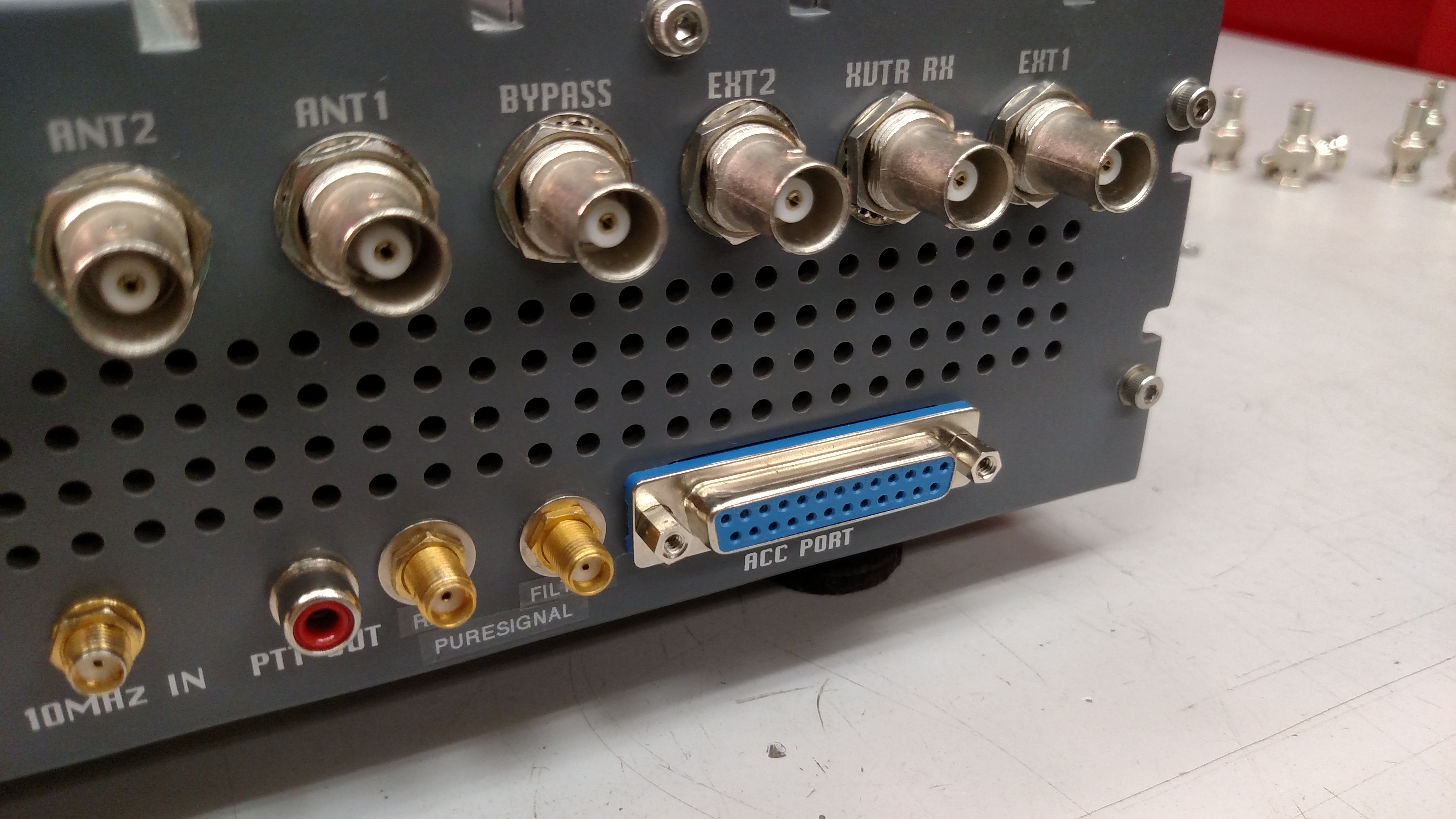
The stock mounting position of the
DB25 accessory port connector, mounted to the inside surface of the
radio rear panel, makes it all but impossible to achieve reliable
connections. The rear panel is quite thick, and this has the effect of
pushing the mounting standoffs too far from the mating surface of the
connector, and therefore most cable connectors will not seat deeply
enough for the pins to mate.
Some people have taken a Dremel tool to the mounting standoffs, but then they become so thin that they can't be used to lock a mating connector into place. It's a half step, at best. Others have taken a Dremel to the mating connector to remove their mounting provisions. Again, another half step.
The correct answer, of course, is to relocate the DB25 connector so that it is mounted to the exterior surface of the radio rear panel, as it should have been from the beginning. Accomplishing this is not difficult, but does take a little bit of time, perhaps an hour or so. I was strongly motivated to do this because I had recently built a cool little accessory unit for my ANAN-100D and couldn't get the high quality, fully shielded, 25 pin cable I bought to fit properly.
DISCLAIMER--you follow this guidance and modify your radio at your own risk. You break it, you bought it, and I didn't twist your arm to do this!
Step 1: Front Panel Disassembly
This is necessary so that the bottom plate can be slid backward for access to the board end of the DB25 ribbon cable connector.
a. Remove all of the fasteners from the front panel.
b. Carefully pull and wiggle on the rear body of the power switch until it detaches from the power switch button. I apologize for not having a better description of this process, but even a video would not provide information on how it feels to do this. WARNING: be careful not to snap the mounts off of the switch body. It should not be necessary to use any tools.
c. Lay the front panel aside.
Step 2: Rear Panel Disassembly
It is desirable to completely remove the rear panel as it makes it much easier to rework the DB25 connector hole that way.
a. Remove all of the nuts and lock washers from the BNC connectors on the rear panel.
b. Remove all of the rear panel fasteners.
c. Pull the rear panel away from the radio.
d. Mark the 10MHz and XVTR cables so you don't mix them up during re-assembly.
e. Remove the nuts and washers on the 10MHz and XVTR SMA connectors and pull the cable assemblies free of the panel.
f. Remove the shrink sleeving at the PTT connector and unsolder the PTT connector wire.
e. Remove the DB25 mounting hardware--note that this can be quite tricky, as Apache used very high strength thread-locking compound on these fasteners.
Step 3: Remove DB25 Cable Assembly
a. Minding all of the various cables and connections inside the radio, none of which should need to be undone, carefully slide the bottom plate assembly rearward until you can reach the board end of the DB25 cable assembly.
b. Mark the orientation of the cable assembly and make note of the board end connector location before disconnecting it. A cell phone photo works quite well for this.
c. Remove the board end of the connector assembly from the board.
Step 4: Rework the Existing DB25 Connector Hole
WARNING: this rework should probably take place away from the near the radio as you do not want to send any metal filings into the radio.
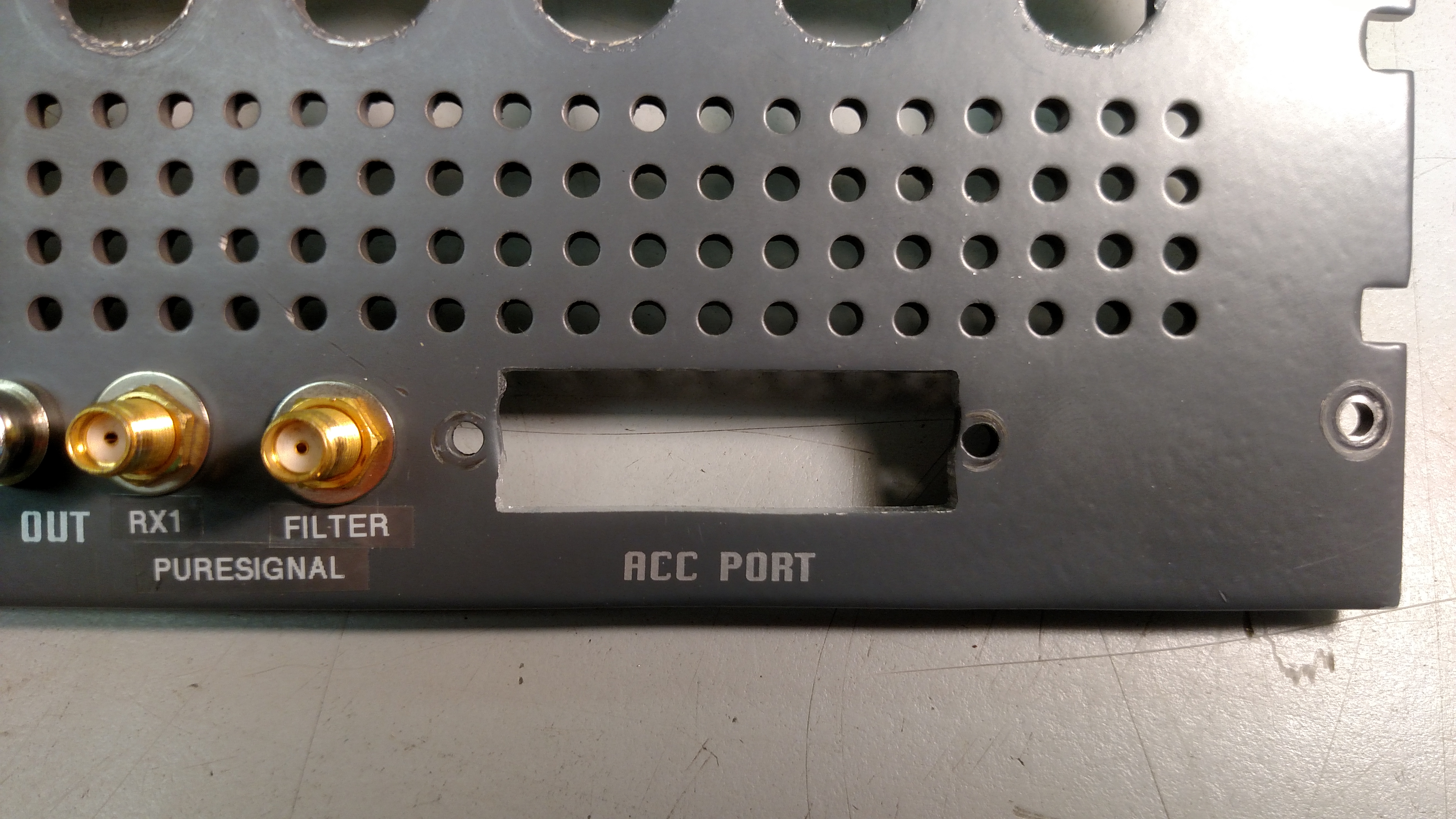
This is the step that actually takes the longest, at least it does if you want to obtain a high quality result. Because the existing connector does not have any flange at the top and bottom edges, you want to achieve a very close, dare I say precision, fit on those surfaces. The left and right surfaces are flanged, so those edges can be a bit rough and no one will ever know except you!
To do this I recommend hand filing. With a good set of files it will not take long, as the rear panel alloy is quite soft. So soft that it would be very easy to make a mistake with a Dremel tool. However, if you want to go to town with a Dremel and don't care what things look like that is entirely up to you.
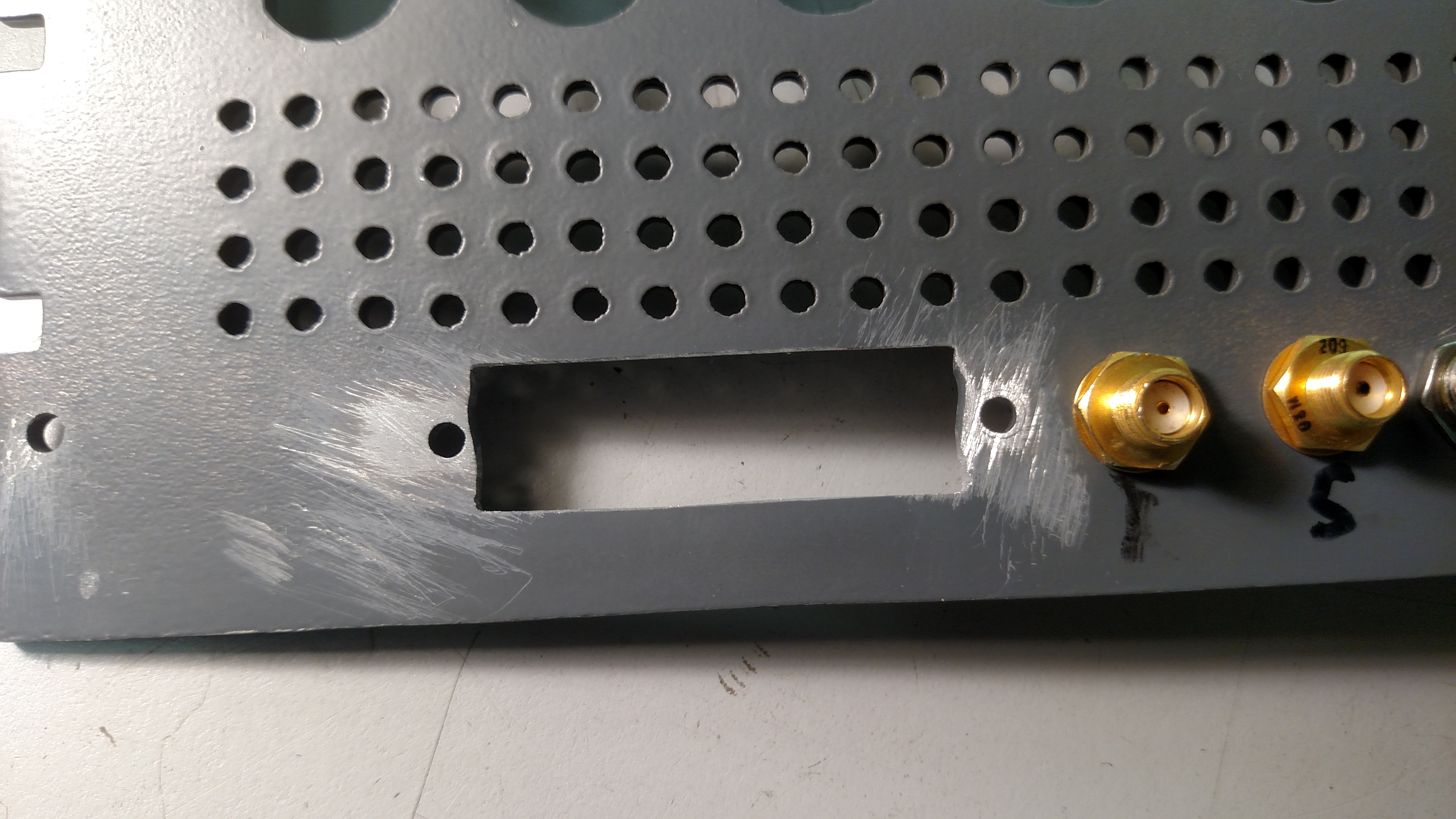
There's not a lot of magic involved, here. Get a file and square the hole off, then enlarge as required. I would file for a bit, then check the fit with the actual connector, and repeat that pattern many, many times. Obviously it is important to keep the top and bottom edges straight, flat and parallel. A larger file is usually better than a smaller file in achieving that. As you get closer to the final dimensions, file less and check the fit more often. Here is what my final result looked like before reassembly. Not quite perfect, but pretty close (see also the first photo above).
I also sanded down the hardware mounting locations on the interior of the panel so that the connector shell made a better ground connection.
Step 5: Assemble the DB25 Cable Assembly to the Rear Panel
a. Insert the DB25 cable assembly from the exterior of the panel.
b. Clean off the excess thread-locking compound from the fasteners.
c. Reassemble connector to the panel with the fasteners and the standoffs. WARNING: the thread-locking compound can prevent reassembly just as well as it can prevent disassembly. Do not use a lot of force because, again, the cheap alloy used on these fasteners is likely to break. If necessary, stop and clean the fasteners again. Or simply use all new hardware.
Step 6: Reassemble the DB25 Cable Assembly to the Board
a. Using the photo you made in Step 3(b) above, reconnect the board end of the cable assembly to the board header connector. Be certain to get the connector properly lined up on the connector so that all of the pins engage.
b. Slide the bottom plate assembly back into place.
Step 6: Rear Panel Assembly
a. Solder the PTT wire back onto the PTT connector. Don't forget the shrink sleeving (it mostly acts as a strain relief).
b. Minding the markings you made in Step 2(d) above, reinstall the XVTR and 10MHz cable assemblies. SMA connector hardware does not require a lot of torque.
c. Minding cable routing as you do so (don't fold or pinch anything), reattach the rear panel to the radio using the rear panel fasteners.
d. Reinstall the BNC connector hardware. This hardware also does not require a lot of torque.
Step 7: Front Panel Assembly
a. Snap the power switch back into the button assembly.
b. Reattach the front panel using the front panel fasteners.
Step 8: Test and Enjoy!
a. Be sure to thoroughly test out all aspects of your radio, as you did just have it apart in many pieces.
b. Enjoy your new, easy to access, properly mounted, DB25 accessory connector.
Some people have taken a Dremel tool to the mounting standoffs, but then they become so thin that they can't be used to lock a mating connector into place. It's a half step, at best. Others have taken a Dremel to the mating connector to remove their mounting provisions. Again, another half step.
The correct answer, of course, is to relocate the DB25 connector so that it is mounted to the exterior surface of the radio rear panel, as it should have been from the beginning. Accomplishing this is not difficult, but does take a little bit of time, perhaps an hour or so. I was strongly motivated to do this because I had recently built a cool little accessory unit for my ANAN-100D and couldn't get the high quality, fully shielded, 25 pin cable I bought to fit properly.
DISCLAIMER--you follow this guidance and modify your radio at your own risk. You break it, you bought it, and I didn't twist your arm to do this!
Step 1: Front Panel Disassembly
This is necessary so that the bottom plate can be slid backward for access to the board end of the DB25 ribbon cable connector.
a. Remove all of the fasteners from the front panel.
b. Carefully pull and wiggle on the rear body of the power switch until it detaches from the power switch button. I apologize for not having a better description of this process, but even a video would not provide information on how it feels to do this. WARNING: be careful not to snap the mounts off of the switch body. It should not be necessary to use any tools.
c. Lay the front panel aside.
Step 2: Rear Panel Disassembly
It is desirable to completely remove the rear panel as it makes it much easier to rework the DB25 connector hole that way.
a. Remove all of the nuts and lock washers from the BNC connectors on the rear panel.
b. Remove all of the rear panel fasteners.
c. Pull the rear panel away from the radio.
d. Mark the 10MHz and XVTR cables so you don't mix them up during re-assembly.
e. Remove the nuts and washers on the 10MHz and XVTR SMA connectors and pull the cable assemblies free of the panel.
f. Remove the shrink sleeving at the PTT connector and unsolder the PTT connector wire.
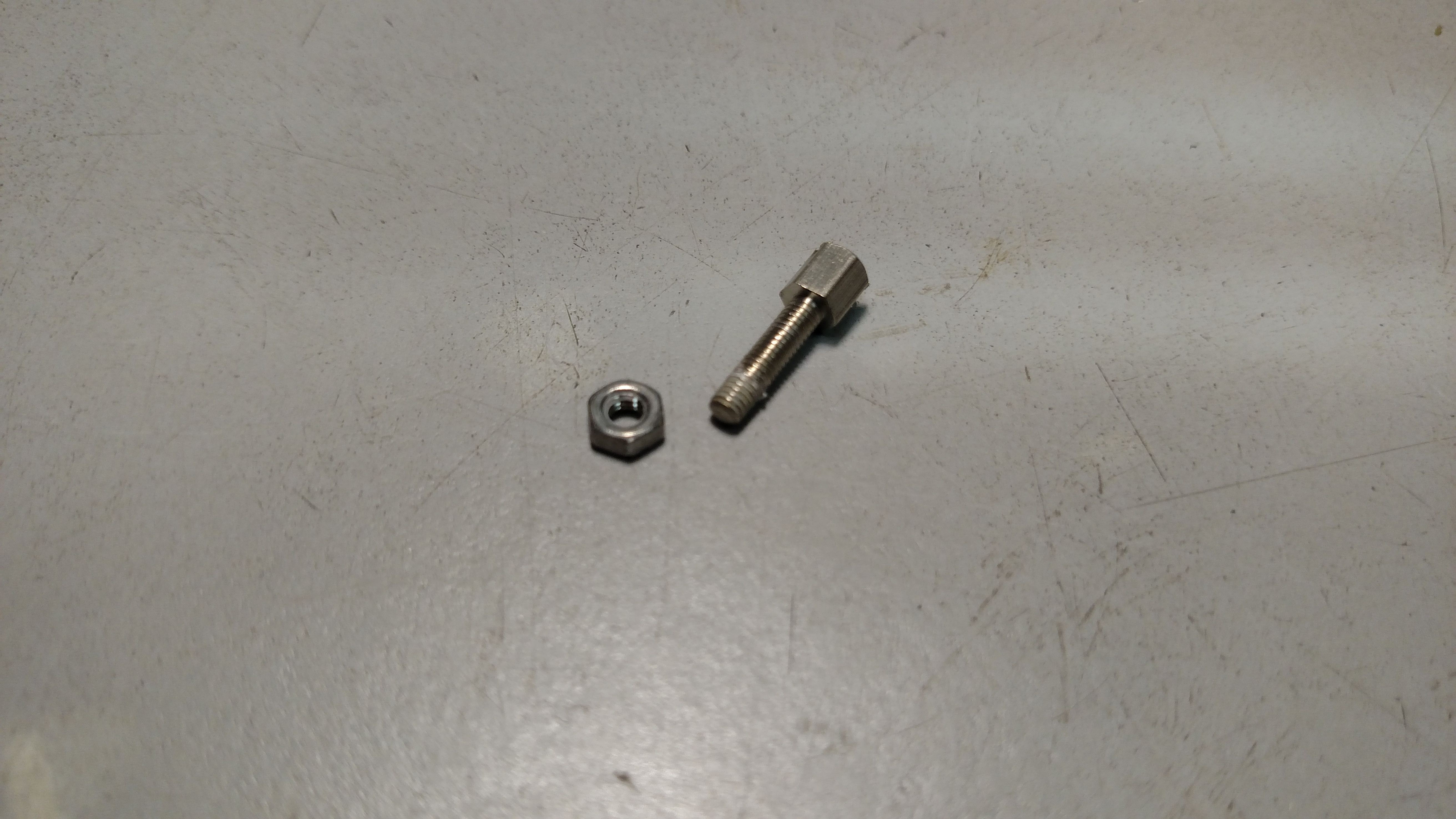
e. Remove the DB25 mounting hardware--note that this can be quite tricky, as Apache used very high strength thread-locking compound on these fasteners.
i. Heat the head of the fastener going
into the standoff with the tip of a soldering iron to melt the
thread-locking compound.
ii. Remove the fastener from the standoff. If it is difficult to turn, return to the heating step above. WARNING: don't force it, as the hardware is a very cheap alloy and will break right in half if a lot of force is applied! Indeed, it might be good to have some spare DB25 mounting hardware on hand, just in case you get impatient! Also, try not to burn yourself on the hot hardware!
ii. Remove the fastener from the standoff. If it is difficult to turn, return to the heating step above. WARNING: don't force it, as the hardware is a very cheap alloy and will break right in half if a lot of force is applied! Indeed, it might be good to have some spare DB25 mounting hardware on hand, just in case you get impatient! Also, try not to burn yourself on the hot hardware!
Step 3: Remove DB25 Cable Assembly
a. Minding all of the various cables and connections inside the radio, none of which should need to be undone, carefully slide the bottom plate assembly rearward until you can reach the board end of the DB25 cable assembly.
b. Mark the orientation of the cable assembly and make note of the board end connector location before disconnecting it. A cell phone photo works quite well for this.
c. Remove the board end of the connector assembly from the board.
Step 4: Rework the Existing DB25 Connector Hole
WARNING: this rework should probably take place away from the near the radio as you do not want to send any metal filings into the radio.
This is the step that actually takes the longest, at least it does if you want to obtain a high quality result. Because the existing connector does not have any flange at the top and bottom edges, you want to achieve a very close, dare I say precision, fit on those surfaces. The left and right surfaces are flanged, so those edges can be a bit rough and no one will ever know except you!
To do this I recommend hand filing. With a good set of files it will not take long, as the rear panel alloy is quite soft. So soft that it would be very easy to make a mistake with a Dremel tool. However, if you want to go to town with a Dremel and don't care what things look like that is entirely up to you.
There's not a lot of magic involved, here. Get a file and square the hole off, then enlarge as required. I would file for a bit, then check the fit with the actual connector, and repeat that pattern many, many times. Obviously it is important to keep the top and bottom edges straight, flat and parallel. A larger file is usually better than a smaller file in achieving that. As you get closer to the final dimensions, file less and check the fit more often. Here is what my final result looked like before reassembly. Not quite perfect, but pretty close (see also the first photo above).
I also sanded down the hardware mounting locations on the interior of the panel so that the connector shell made a better ground connection.
Step 5: Assemble the DB25 Cable Assembly to the Rear Panel
a. Insert the DB25 cable assembly from the exterior of the panel.
b. Clean off the excess thread-locking compound from the fasteners.
c. Reassemble connector to the panel with the fasteners and the standoffs. WARNING: the thread-locking compound can prevent reassembly just as well as it can prevent disassembly. Do not use a lot of force because, again, the cheap alloy used on these fasteners is likely to break. If necessary, stop and clean the fasteners again. Or simply use all new hardware.
Step 6: Reassemble the DB25 Cable Assembly to the Board
a. Using the photo you made in Step 3(b) above, reconnect the board end of the cable assembly to the board header connector. Be certain to get the connector properly lined up on the connector so that all of the pins engage.
b. Slide the bottom plate assembly back into place.
Step 6: Rear Panel Assembly
a. Solder the PTT wire back onto the PTT connector. Don't forget the shrink sleeving (it mostly acts as a strain relief).
b. Minding the markings you made in Step 2(d) above, reinstall the XVTR and 10MHz cable assemblies. SMA connector hardware does not require a lot of torque.
c. Minding cable routing as you do so (don't fold or pinch anything), reattach the rear panel to the radio using the rear panel fasteners.
d. Reinstall the BNC connector hardware. This hardware also does not require a lot of torque.
Step 7: Front Panel Assembly
a. Snap the power switch back into the button assembly.
b. Reattach the front panel using the front panel fasteners.
Step 8: Test and Enjoy!
a. Be sure to thoroughly test out all aspects of your radio, as you did just have it apart in many pieces.
b. Enjoy your new, easy to access, properly mounted, DB25 accessory connector.