Introduction
The openHPSDR architecture radios all
contain two FPGA images that they can boot from. The normal image is
the one that is used to run the radio under normal circumstances.
This
image is user programmable by means of the HPSDR Programmer
application. However, because this image is user programmable, that
makes it susceptible to a failed programming cycle. A failure to
program the image properly could be caused by any interruption in the
programming process, such as a power failure, an Ethernet problem, or a
PC crash during programming. The result is an apparently "bricked"
radio, slang for a radio with a corrupted FPGA image. Such a radio is
no better, smarter or more functional than the proverbial brick!
Thankfully, the designers of the openHPSDR architecture radios provided a back-up mechanism in the event that the user programmable FPGA image is corrupted. This back-up mechanism is an alternate FPGA image called the "Bootloader". The Bootloader image is not normally user programmable (at least not without opening the radio and attaching a JTAG programming pod). Hence it is essentially immune from user meddling and thereby always available for use in case the normal image is bricked or otherwise not usable.
The 10E, 100B, 200D and 8000DLE have an external switch that can be accessed by the user to select which image the radio FPGA should boot up with, normal or Bootloader. Hermes and Angelia based radios, such as the 10, 100 and 100D, do not have this switch, and require one to physically open up the radio and place a jumper on the Hermes or Angelia circuit card. This is, at the very least, a huge pain in the posterior. More seriously, every time you open the radio there is some risk of damaging something. This is particularly true on the 100W radios, as the cable routing is complex and difficult to work with.
The correct answer, of course, is to take the radio apart one time to install an external switch in place of a jumper. It is even possible to do this in the form of a small jack, into which you could insert a shorted plug, or even wire the plug to a relay of some sort for remote control. Pictured below is the switch I added to the rear panel of my 100D.

What follows are instructions for how to install a Bootloader switch on an ANAN-100D. The steps should be similar on an ANAN-100, and easier on an ANAN-10.
DISCLAIMER--you follow this guidance and modify your radio at your own risk. You break it, you bought it, and I didn't twist your arm to do this!
Step 1: Front Panel Disassembly
This is necessary so that the bottom plate can be slid forwards and backwards for access.
a. Remove all of the fasteners from the front panel.
b. Carefully pull and wiggle on the rear body of the power switch until it detaches from the power switch button. I apologize for not having a better description of this process, but even a video would not provide information on how it feels to do this. WARNING: be careful not to snap the mounts off of the switch body. It should not be necessary to use any tools.
c. Lay the front panel aside.
Step 2: Rear Panel Disassembly
It is desirable to completely remove the rear panel as it makes it much easier and safer to drill the hole for the new switch that way.
a. Remove all of the nuts and lock washers from the BNC connectors on the rear panel.
b. Remove all of the rear panel fasteners.
c. Pull the rear panel away from the radio.
d. Mark the 10MHz and XVTR cables so you don't mix them up during re-assembly.
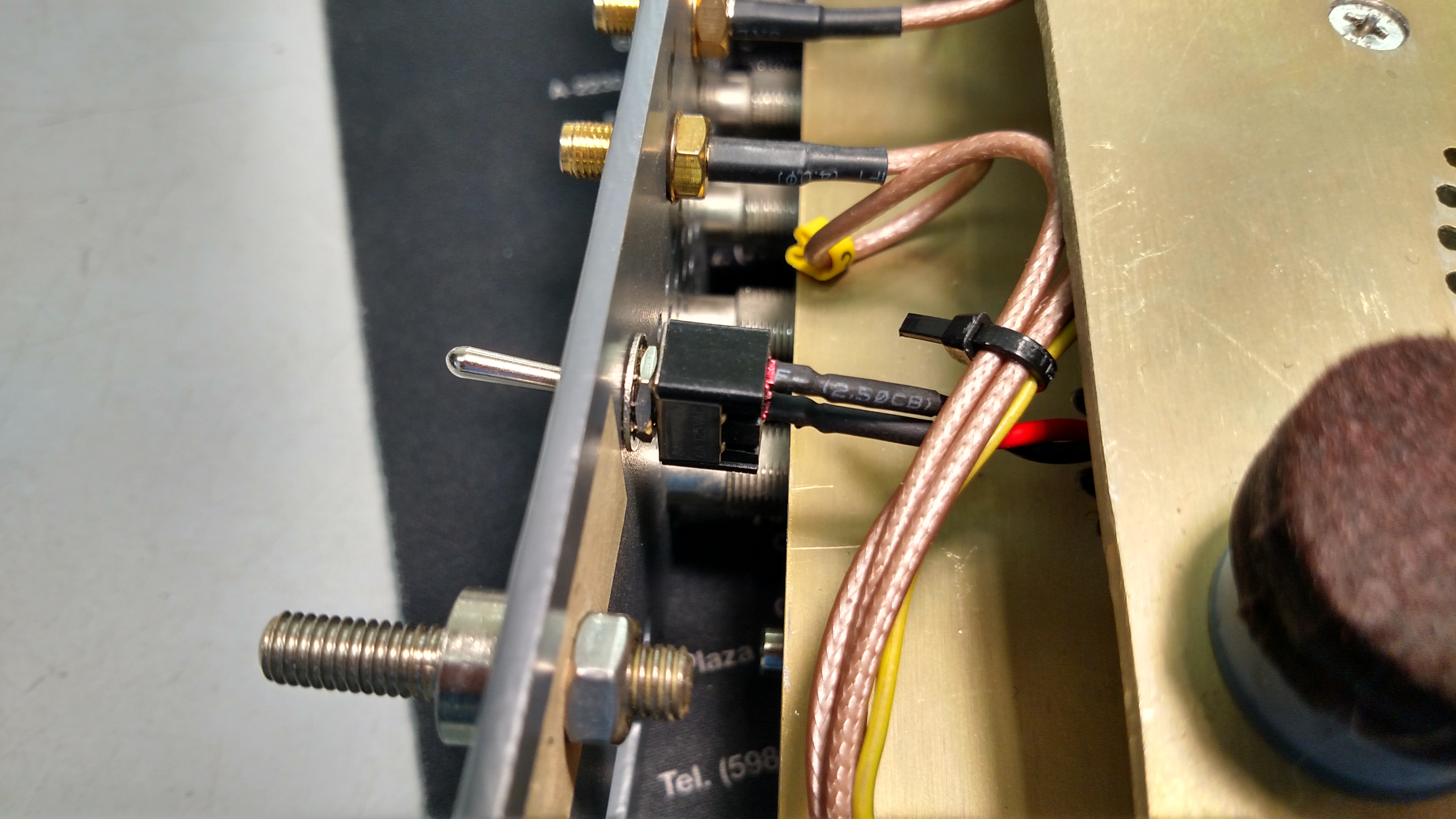
e. Remove the nuts and washers on the 10MHz and XVTR SMA connectors and pull the cable assemblies free of the panel.
f. Remove the shrink sleeving at the PTT connector and unsolder the PTT connector wire.
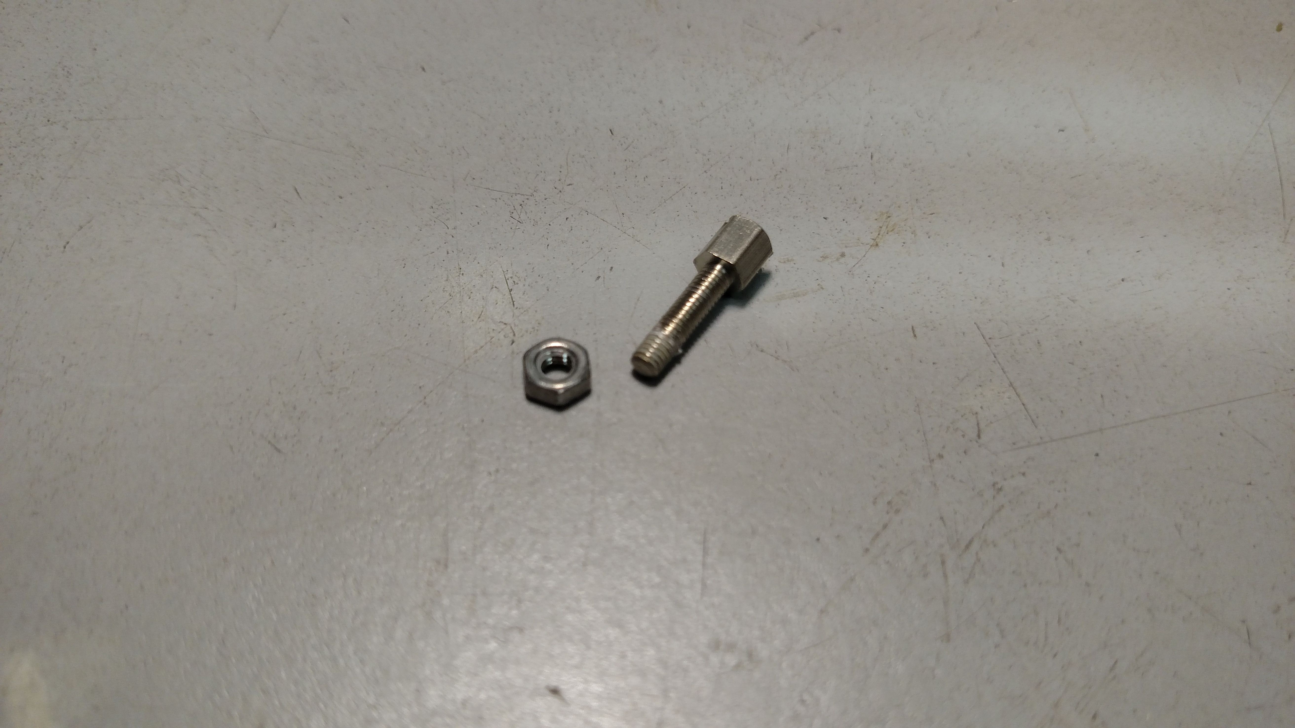
e. Remove the DB25 mounting hardware--note that this can be quite tricky, as Apache used very high strength thread-locking compound on these fasteners.
Step 3: Remove DB25 Cable Assembly
a. Minding all of the various cables and connections inside the radio, none of which should need to be undone, carefully slide the bottom plate assembly rearward until you can reach the board end of the DB25 cable assembly.
b. Mark the orientation of the cable assembly and make note of the board end connector location before disconnecting it. A cell phone photo works quite well for this.
c. Remove the board end of the connector assembly from the board.
Step 4: Drill the Hole for the Switch
WARNING: this rework should probably take place away from the radio as you do not want to send any metal filings into the radio.
There's not a lot of magic involved, here. Choose a place on the rear panel such that the body of the switch will fit when the panel is assembled onto the chassis. This should not be a problem for most sub-miniature switches. The location shown in my photo above is generally a good location.
Step 5: Assembly the Switch/Jumper Connector Wiring Harness
Obtain some suitable wire, an SPST sub-miniature switch, and a couple of PC board jumpers. Solder a wire to one jumper and then to one side of the switch. Solder another wire to the other jumper and then to the other side of the switch. Obviously the wire needs to be long enough to allow it to reach from the jumper location on the board (in this example Angelia J17) to the rear panel, plus a little extra to allow for future disassembly. I have found that it helps to twist the wires together to keep it neat and organized.
Step 6: Install the Switch/Jumper Assembly
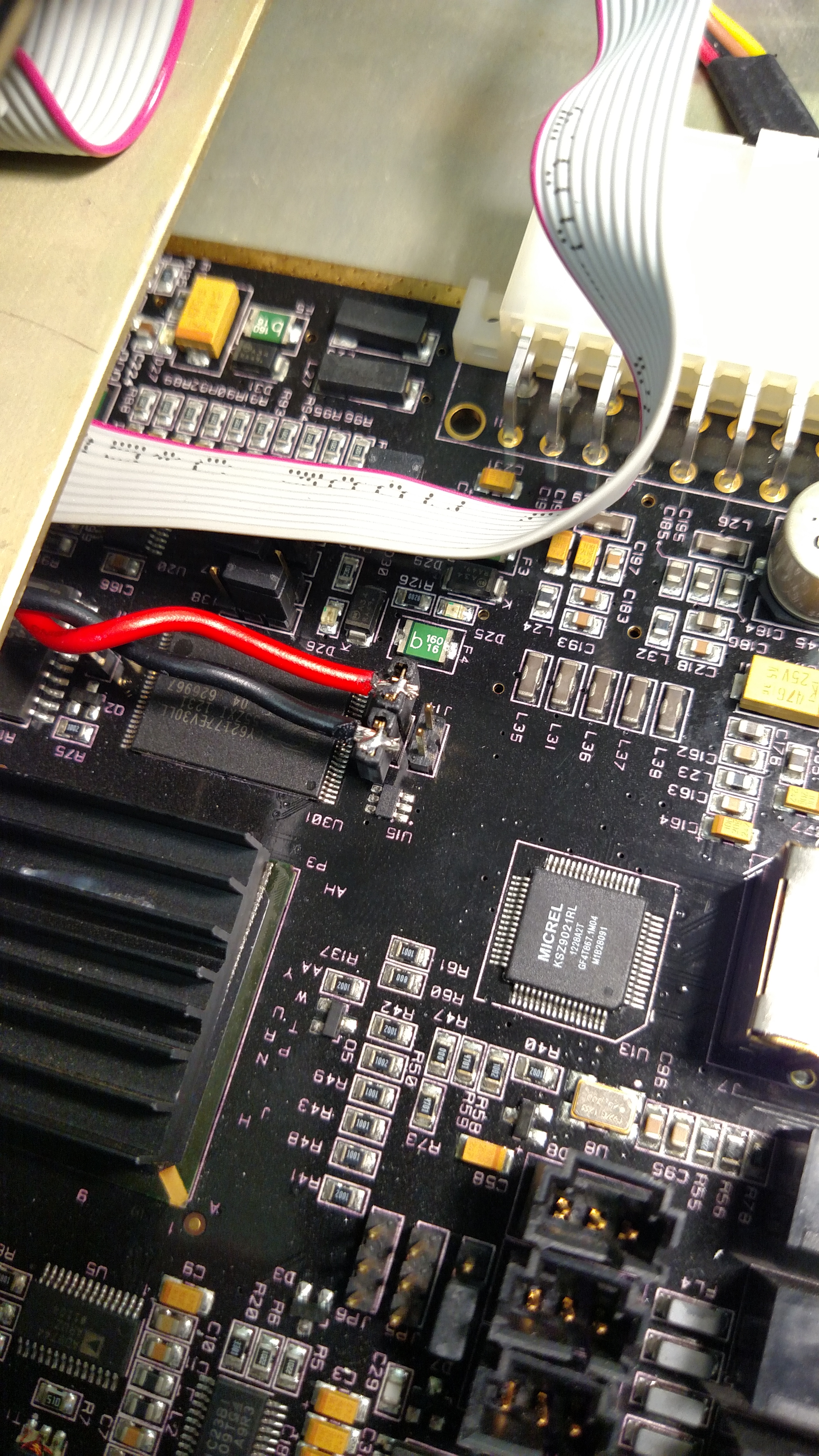
Install the switch into the rear panel hole that was drilled for it. Bring the rear panel close to the chassis and route the wires over the top of the Angelia card. Carefully slide the bottom plate assembly forward far enough to install one jumper onto each jumper pin (J17 on the Angelia). Refer to your manual for jumper information. On page 57 it calls out J17 for the 100D. On page 69 it shows the location. Be careful of all of the wiring when sliding the bottom plate assembly around.
Step 7: Assemble the DB25 Cable Assembly to the Rear Panel
a. Insert the DB25 cable assembly from the exterior of the panel.
b. Clean off the excess thread-locking compound from the fasteners.
c. Reassemble connector to the panel with the fasteners and the standoffs. WARNING: the thread-locking compound can prevent reassembly just as well as it can prevent disassembly. Do not use a lot of force because, again, the cheap alloy used on these fasteners is likely to break. If necessary, stop and clean the fasteners again. Or simply use all new hardware.
Step 8: Reassemble the DB25 Cable Assembly to the Board
a. Using the photo you made in Step 3(b) above, reconnect the board end of the cable assembly to the board header connector. Be certain to get the connector properly lined up on the connector so that all of the pins engage.
b. Slide the bottom plate assembly back into place.
Step 9: Rear Panel Assembly
a. Solder the PTT wire back onto the PTT connector. Don't forget the shrink sleeving (it mostly acts as a strain relief).
b. Minding the markings you made in Step 2(d) above, reinstall the XVTR and 10MHz cable assemblies. SMA connector hardware does not require a lot of torque.
c. Minding cable routing as you do so (don't fold or pinch anything), reattach the rear panel to the radio using the rear panel fasteners.
d. Reinstall the BNC connector hardware. This hardware also does not require a lot of torque.
Step 10: Front Panel Assembly
a. Snap the power switch back into the button assembly.
b. Reattach the front panel using the front panel fasteners.
Step 11: Test and Enjoy!
Be sure to thoroughly test out all aspects of your radio, as you did just have it apart in many pieces. You do not need to reload firmware using the Bootloader to test that the switch works. It is enough to confirm that the Bootloader application can detect the radio. To do that follow the instructions below as far as Step 7. Then skip forward to Step 10.
NOTE: Bootloader mode will NOT work if you use a managed Ethernet switch. In bootloader mode the radio advertises a MAC address of 11:22:33:44:55:66. This is an illegal MAC address and managed switches will not route packets to that address. Use a dumb switch or a direct connection.
Bootloader instructions:
1. Download and install WinPCAP (Bootloader requires it).
2. Download and install HPSDR Bootloader.
3. Power off radio.
4. Move bootloader switch to bootloader position.
5. Power up radio.
6. Run Bootloader.
7. Click "Test for Bootloader". Bootloader should discover the radio.
8. Click "Browse" in the Board Programmer section. Select the rbf file you want. You may need to change the name of the rbf file to "metis.rbf". Nobody knows why.
9. Click "Program" in the Board Programmer section. Wait for it to complete.
10. Quit Bootloader.
11. Power off radio.
12. Move bootloader switch back to normal position.
13. Power up the radio and enjoy!
Thankfully, the designers of the openHPSDR architecture radios provided a back-up mechanism in the event that the user programmable FPGA image is corrupted. This back-up mechanism is an alternate FPGA image called the "Bootloader". The Bootloader image is not normally user programmable (at least not without opening the radio and attaching a JTAG programming pod). Hence it is essentially immune from user meddling and thereby always available for use in case the normal image is bricked or otherwise not usable.
The 10E, 100B, 200D and 8000DLE have an external switch that can be accessed by the user to select which image the radio FPGA should boot up with, normal or Bootloader. Hermes and Angelia based radios, such as the 10, 100 and 100D, do not have this switch, and require one to physically open up the radio and place a jumper on the Hermes or Angelia circuit card. This is, at the very least, a huge pain in the posterior. More seriously, every time you open the radio there is some risk of damaging something. This is particularly true on the 100W radios, as the cable routing is complex and difficult to work with.
The correct answer, of course, is to take the radio apart one time to install an external switch in place of a jumper. It is even possible to do this in the form of a small jack, into which you could insert a shorted plug, or even wire the plug to a relay of some sort for remote control. Pictured below is the switch I added to the rear panel of my 100D.
What follows are instructions for how to install a Bootloader switch on an ANAN-100D. The steps should be similar on an ANAN-100, and easier on an ANAN-10.
DISCLAIMER--you follow this guidance and modify your radio at your own risk. You break it, you bought it, and I didn't twist your arm to do this!
Step 1: Front Panel Disassembly
This is necessary so that the bottom plate can be slid forwards and backwards for access.
a. Remove all of the fasteners from the front panel.
b. Carefully pull and wiggle on the rear body of the power switch until it detaches from the power switch button. I apologize for not having a better description of this process, but even a video would not provide information on how it feels to do this. WARNING: be careful not to snap the mounts off of the switch body. It should not be necessary to use any tools.
c. Lay the front panel aside.
Step 2: Rear Panel Disassembly
It is desirable to completely remove the rear panel as it makes it much easier and safer to drill the hole for the new switch that way.
a. Remove all of the nuts and lock washers from the BNC connectors on the rear panel.
b. Remove all of the rear panel fasteners.
c. Pull the rear panel away from the radio.
d. Mark the 10MHz and XVTR cables so you don't mix them up during re-assembly.
e. Remove the nuts and washers on the 10MHz and XVTR SMA connectors and pull the cable assemblies free of the panel.
f. Remove the shrink sleeving at the PTT connector and unsolder the PTT connector wire.
e. Remove the DB25 mounting hardware--note that this can be quite tricky, as Apache used very high strength thread-locking compound on these fasteners.
i. Heat the head of the fastener going
into the standoff with the tip of a soldering iron to melt the
thread-locking compound.
ii. Remove the fastener from the standoff. If it is difficult to turn, return to the heating step above. WARNING: don't force it, as the hardware is a very cheap alloy and will break right in half if a lot of force is applied! Indeed, it might be good to have some spare DB25 mounting hardware on hand, just in case you get impatient! Also, try not to burn yourself on the hot hardware!
ii. Remove the fastener from the standoff. If it is difficult to turn, return to the heating step above. WARNING: don't force it, as the hardware is a very cheap alloy and will break right in half if a lot of force is applied! Indeed, it might be good to have some spare DB25 mounting hardware on hand, just in case you get impatient! Also, try not to burn yourself on the hot hardware!
Step 3: Remove DB25 Cable Assembly
a. Minding all of the various cables and connections inside the radio, none of which should need to be undone, carefully slide the bottom plate assembly rearward until you can reach the board end of the DB25 cable assembly.
b. Mark the orientation of the cable assembly and make note of the board end connector location before disconnecting it. A cell phone photo works quite well for this.
c. Remove the board end of the connector assembly from the board.
Step 4: Drill the Hole for the Switch
WARNING: this rework should probably take place away from the radio as you do not want to send any metal filings into the radio.
There's not a lot of magic involved, here. Choose a place on the rear panel such that the body of the switch will fit when the panel is assembled onto the chassis. This should not be a problem for most sub-miniature switches. The location shown in my photo above is generally a good location.
Step 5: Assembly the Switch/Jumper Connector Wiring Harness
Obtain some suitable wire, an SPST sub-miniature switch, and a couple of PC board jumpers. Solder a wire to one jumper and then to one side of the switch. Solder another wire to the other jumper and then to the other side of the switch. Obviously the wire needs to be long enough to allow it to reach from the jumper location on the board (in this example Angelia J17) to the rear panel, plus a little extra to allow for future disassembly. I have found that it helps to twist the wires together to keep it neat and organized.
Step 6: Install the Switch/Jumper Assembly
Install the switch into the rear panel hole that was drilled for it. Bring the rear panel close to the chassis and route the wires over the top of the Angelia card. Carefully slide the bottom plate assembly forward far enough to install one jumper onto each jumper pin (J17 on the Angelia). Refer to your manual for jumper information. On page 57 it calls out J17 for the 100D. On page 69 it shows the location. Be careful of all of the wiring when sliding the bottom plate assembly around.
Step 7: Assemble the DB25 Cable Assembly to the Rear Panel
a. Insert the DB25 cable assembly from the exterior of the panel.
b. Clean off the excess thread-locking compound from the fasteners.
c. Reassemble connector to the panel with the fasteners and the standoffs. WARNING: the thread-locking compound can prevent reassembly just as well as it can prevent disassembly. Do not use a lot of force because, again, the cheap alloy used on these fasteners is likely to break. If necessary, stop and clean the fasteners again. Or simply use all new hardware.
Step 8: Reassemble the DB25 Cable Assembly to the Board
a. Using the photo you made in Step 3(b) above, reconnect the board end of the cable assembly to the board header connector. Be certain to get the connector properly lined up on the connector so that all of the pins engage.
b. Slide the bottom plate assembly back into place.
Step 9: Rear Panel Assembly
a. Solder the PTT wire back onto the PTT connector. Don't forget the shrink sleeving (it mostly acts as a strain relief).
b. Minding the markings you made in Step 2(d) above, reinstall the XVTR and 10MHz cable assemblies. SMA connector hardware does not require a lot of torque.
c. Minding cable routing as you do so (don't fold or pinch anything), reattach the rear panel to the radio using the rear panel fasteners.
d. Reinstall the BNC connector hardware. This hardware also does not require a lot of torque.
Step 10: Front Panel Assembly
a. Snap the power switch back into the button assembly.
b. Reattach the front panel using the front panel fasteners.
Step 11: Test and Enjoy!
Be sure to thoroughly test out all aspects of your radio, as you did just have it apart in many pieces. You do not need to reload firmware using the Bootloader to test that the switch works. It is enough to confirm that the Bootloader application can detect the radio. To do that follow the instructions below as far as Step 7. Then skip forward to Step 10.
NOTE: Bootloader mode will NOT work if you use a managed Ethernet switch. In bootloader mode the radio advertises a MAC address of 11:22:33:44:55:66. This is an illegal MAC address and managed switches will not route packets to that address. Use a dumb switch or a direct connection.
Bootloader instructions:
1. Download and install WinPCAP (Bootloader requires it).
2. Download and install HPSDR Bootloader.
3. Power off radio.
4. Move bootloader switch to bootloader position.
5. Power up radio.
6. Run Bootloader.
7. Click "Test for Bootloader". Bootloader should discover the radio.
8. Click "Browse" in the Board Programmer section. Select the rbf file you want. You may need to change the name of the rbf file to "metis.rbf". Nobody knows why.
9. Click "Program" in the Board Programmer section. Wait for it to complete.
10. Quit Bootloader.
11. Power off radio.
12. Move bootloader switch back to normal position.
13. Power up the radio and enjoy!